 |
ac3wzw00005085
TURBOCHARGER WITH VARIABLE TURBINE GEOMETRY REMOVAL/INSTALLATION [SKYACTIV-D 1.8]
id0113q9707500
Replacement Part
|
Gasket
Quantity: 1
Location of use: Turbocharger with variable turbine geometry
|
Nut
Quantity: 3
Location of use: Turbocharger with variable turbine geometry
|
Gasket
Quantity: 1
Location of use: Oil return pipe No.1
|
|
Gasket
Quantity: 1
Location of use: Oil return pipe No.2
|
—
|
—
|
Operation After Replacing or Removal/Installation Turbocharger
1. If the turbocharger is replaced or removed/installed, perform the following procedure.
|
STEP |
ACTION |
PAGE/CONDITION |
|---|---|---|
|
1
|
Switch the ignition off.
|
—
|
|
2
|
Wait for 30 s.
|
—
|
|
3
|
Start the engine.
|
—
|
|
4
|
Maintain the engine idling condition for 10 s.
|
—
|
|
5
|
Switch the ignition off.
|
—
|
|
6
|
Wait for 30 s.
|
—
|
|
7
|
Perform KOER self-test procedure.
|
(See DTC INSPECTION.)
|
Turbocharger With Variable Turbine Geometry Removal/Installation
1. Disconnect the negative battery terminal. (See NEGATIVE BATTERY TERMINAL DISCONNECTION/CONNECTION [(E)].)
2. Remove the engine cover. (See ENGINE COVER REMOVAL/INSTALLATION [SKYACTIV-D 1.8].)
3. Drain the engine coolant. (See ENGINE COOLANT REPLACEMENT [SKYACTIV-D 1.8].)
4. Remove the following parts: (See INTAKE-AIR SYSTEM REMOVAL/INSTALLATION [SKYACTIV-D 1.8].)
5. Remove the battery and the battery tray. (See BATTERY REMOVAL/INSTALLATION [SKYACTIV-D 1.8].)
6. Remove the following parts as a single unit: (See INTAKE-AIR SYSTEM REMOVAL/INSTALLATION [SKYACTIV-D 1.8].)
7. Remove the turbocharger air outlet pipe. (See INTAKE-AIR SYSTEM REMOVAL/INSTALLATION [SKYACTIV-D 1.8].)
8. Remove the front crossmember. (See FRONT CROSSMEMBER REMOVAL/INSTALLATION [(E)].)
9. Remove the catalytic converter (DPF). (See EXHAUST SYSTEM REMOVAL/INSTALLATION [SKYACTIV-D 1.8].)
10. Remove the catalytic converter (oxidation catalyst/NOx strage catalyst). (See EXHAUST SYSTEM REMOVAL/INSTALLATION [SKYACTIV-D 1.8] .)
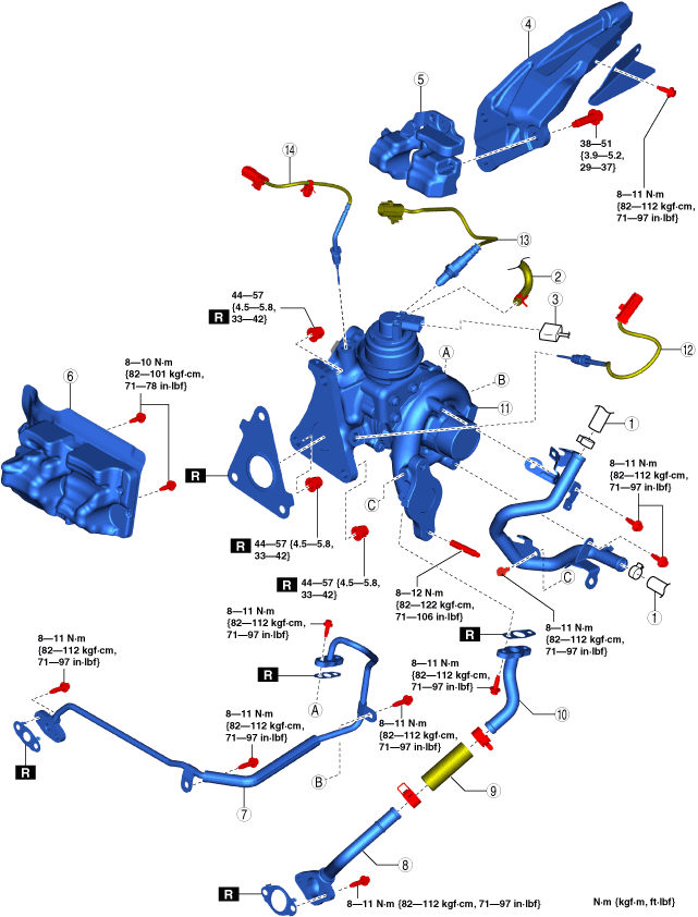
11. Remove in the order shown in the figure.
12. Install in the reverse order of removal.
13. Refill the engine coolant. (See ENGINE COOLANT REPLACEMENT [SKYACTIV-D 1.8].)
14. Perform the following procedure.
ac3wzw00005085
|
|
1
|
Heater hose
|
|
2
|
Vacuum hose
|
|
3
|
Turbocharger actuator connector
|
|
4
|
Turbocharger bracket
|
|
5
|
Insulator
|
|
6
|
Insulator
|
|
7
|
Oil main pipe
|
|
8
|
Oil return pipe No.1
|
|
9
|
Oil return hose
|
|
10
|
Oil return pipe No.2
|
|
11
|
Turbocharger with variable turbine geometry
|
|
12
|
Exhaust gas temperature sensor No.1
|
|
13
|
A/F sensor
|
|
14
|
Exhaust gas temperature sensor No.2
|
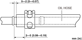
Oil Return Hose Installation Note
1. Install the oil return hose as shown in the figure.
ac3wzw00004684
|
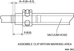
Vacuum hose installation note
1. Install the vacuum hose as shown in the figure.
ac3wzw00004685
|