 |
am3zzw00030224
BATTERY REMOVAL/INSTALLATION [SKYACTIV-G (WITH CYLINDER DEACTIVATION (E))]
id0117008005v3
Replacement Part
|
Set bolt
Quantity: 2
Location of use: PCM cover
|
Operation After Replacing Battery
|
Step |
Action |
|---|---|
|
1
|
Close the all doors.
|
|
2
|
Switch the ignition ON (engine off).
|
|
3
|
If a warning message is displayed in the screen display, clear the screen using the INFO switch and then go to the next step.
|
|
4
|
Shift the selector lever to the N position. (ATX)
Shift the shift lever to the neutral position. (MTX)
|
|
5
|
Perform the following work with the brake pedal depressed.
1. Depress the accelerator pedal for 5 s or more.
2. Verify that a warning message (master warning light) on the screen display flashes.
3. Depress and release the accelerator pedal 3 times.
4. Verify that a warning message (master warning light) on the screen display turn off.
|
|
6
|
Switch the ignition off and disconnect the negative battery terminal. (See NEGATIVE BATTERY TERMINAL DISCONNECTION/CONNECTION [(E)].)
|
|
7
|
Verifying battery condition initialization setting (i-stop setting). (See BATTERY CONDITION INITIALIZATION SETTING (i-stop SETTING).)
|
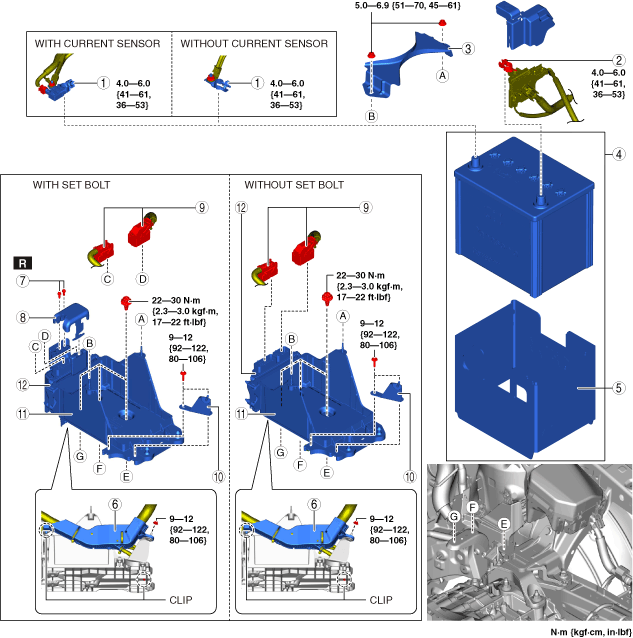
Battery Removal/Installation
1. Remove in the order indicated in the table.
2. Install in the reverse order of removal.
am3zzw00030224
|
|
1
|
Negative battery terminal
|
|
2
|
Positive battery terminal
|
|
3
|
Battery clamp
|
|
4
|
Battery and battery box
|
|
5
|
Battery box
|
|
6
|
Wiring harness
|
|
7
|
Set bolt
(See Set bolt removal note.)
(See Set bolt installation note.)
|
|
8
|
PCM cover
|
|
9
|
PCM connector
|
|
10
|
Bracket
|
|
11
|
Battery tray and PCM component
|
|
12
|
PCM
|
Battery and battery box removal note
Wiring harness disconnection note
1. Remove the following parts as a single unit: (See INTAKE-AIR SYSTEM REMOVAL/INSTALLATION [SKYACTIV-G (WITH CYLINDER DEACTIVATION (E))].)
2. Disconnect the wiring harness.
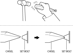
Set bolt removal note
1. Using a chisel and a hammer, cut a groove on the head of the set bolt so that a screwdriver can be inserted.
2. Loose the set bolt using an impact screwdriver or pliers.
ac9wzw00003390
|
Battery tray and PCM component installation note
1. Tighten the battery tray installation bolts in the order shown in the figure.
am3zzw00030364
|
PCM connector connection note
am3zzw00031175
|
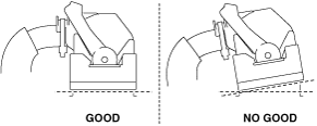
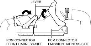
1. Set the PCM connector lever to the position shown in the figure.
am3zzw00032497
|
2. Align the PCM connector straight against the connection surface.
am3zzw00032498
|
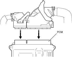
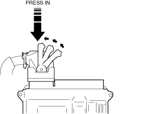
3. Insert the PCM connector straight and press it in until the lever moves up naturally. (Front harness-side connector)
am3zzw00032499
|
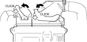
4. Press the PCM connector lever until a click sound is heard.
am3zzw00032500
|
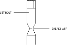
Set bolt installation note
1. Install a new set bolt and tighten it until the neck of the bolt breaks off.
ac9wzw00003391
|
Battery box installation note
1. Install the battery box so that the side with the larger notch is pointed at the engine.
am3zzw00025286
|
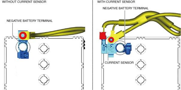
Positive battery terminal connection note
Negative battery terminal connection note
1. Connect the negative battery terminal so that the wiring harness does not block the upper part of the battery filler cap.
am3zzw00030225
|