 |
am3zzw00038047
CONFIGURATION
id990200001100
1. Connect the M-MDS to the DLC-2.
2. Switch the ignition ON (engine off or on).
3. Perform the following procedure using the M-MDS.
4. Select the applicable module according to the module table. (See Module Table.)
5. Perform the configuration following the instructions on the screen.
6. Perform the DTC inspection. (See DTC INSPECTION.)
Outline
Module Table
|
M-MDS display name |
Applicable module |
Configuration method |
Page |
||
|---|---|---|---|---|---|
|
M-MDS [Type A] |
M-MDS and global central configuration (GCC)*1 [Type B] |
Global central configuration (GCC)*1 [Type C] |
|||
|
BCM
|
Body control module (BCM)
|
×
|
—
|
—
|
|
|
PCM
|
PCM
|
×
|
—
|
—
|
|
|
SAS
|
SAS control module
|
×
|
—
|
—
|
|
|
TCM
|
TCM
|
—
|
×
|
—
|
|
|
CCU
|
Climate control unit
(Full-auto air conditioner)
|
—
|
×
|
—
|
|
|
Climate control unit
(Manual air conditioner)
|
—
|
×
|
—
|
||
|
LFU
|
LF control unit
|
—
|
×
|
—
|
|
|
ADD
|
Active driving display
|
—
|
×
|
—
|
|
|
DASH_ESU
|
Dash-electrical supply unit
|
—
|
×
|
—
|
|
|
ESU
|
Electrical supply unit (ESU)
|
—
|
×
|
—
|
|
|
IC
|
Instrument cluster
|
—
|
×
|
—
|
|
|
DSC
|
DSC HU/CM
|
—
|
×
|
—
|
|
|
Electronically controlled brake unit
|
—
|
×
|
—
|
||
|
TCU
|
Telematics communication unit
|
—
|
—
|
×
|
|
|
ALH/AFS/ALV
|
Adaptive front lighting system (AFS) control module
|
—
|
—
|
×
|
|
|
Adaptive LED headlights control module
|
—
|
—
|
×
|
||
|
Auto leveling control module
|
—
|
—
|
×
|
||
|
EPS
|
Electric power steering (EPS) control module
|
—
|
—
|
×
|
|
|
DOOR_ESU_D
|
Door-electrical supply unit (driver-side)
|
—
|
—
|
×
|
|
|
DOOR_ESU_P
|
Door-electrical supply unit (passenger-side)
|
—
|
—
|
×
|
|
|
CMU
|
Connectivity master unit (CMU)
|
—
|
—
|
×
|
|
|
VMC
|
360° view monitor control module
|
—
|
—
|
×
|
|
Configuration Flow
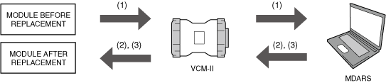
Type A
1. Before replacing a module, perform a read out (1) of items such as the learning values of the cumulative traveled distance or during vehicle use, personalization data, and control programs.
2. After replacing a module, write (2) the software to the module after replacement.
3. Write (3) the data read out before replacing the module to the module after replacement.
am3zzw00038047
|
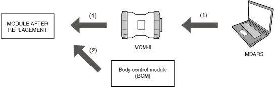
Type B
1. After replacing a module, write (2) the software to the module after replacement.
2. When the ignition is switched ON (engine off or on) after writing the software to the module after replacement, the vehicle information is extracted from the body control module (BCM) and written (2) to the module.
am3zzw00038048
|
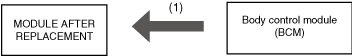
Type C
1. When the ignition is switched ON (engine off or on) after replacing a module, the vehicle information is extracted from the body control module (BCM) and written (1) to the module after replacement.
am3zzw00038049
|