49 B025 010
Attachment A

49 B025 017
Sliding hammer

FRONT DRIVE SHAFT REMOVAL/INSTALLATION [(E)]
id0313008025y2
Special service tool (SST)
|
49 B025 010
Attachment A
|
|
49 B025 017
Sliding hammer
|
|
Replacement part
|
Locknut
Quantity: 1
Location of use: Front drive shaft
|
Snap pin
Quantity: 1
Location of use: Tie-rod end
|
Transfer oil seal (RH) No.1 (AWD)
Quantity: 1
Location of use: Front drive shaft (RH)
|
|
Transfer oil seal (RH) No.3 (AWD)
Quantity: 1
Location of use: Front drive shaft (RH)
|
Front drive shaft clip
Quantity: 1
Location of use: Front drive shaft (LH)
|
—
|
Oil and chemical type
|
Grease
Type: D4Y0 33247 or equivalent
|
1. Remove the wheel and tire. (See WHEEL AND TIRE REMOVAL/INSTALLATION.)
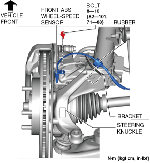
2. Disconnect the rubber from the bracket.
ac30zw00003985
|
3. Disconnect the front ABS wheel-speed sensor wiring harness on the steering knuckle and set it aside so that it does not interfere with the servicing.
4. Remove the front under cover No.2. (See FRONT UNDER COVER No.2 REMOVAL/INSTALLATION.)
5. Remove the front deflector. (See DEFLECTOR REMOVAL/INSTALLATION.)
6. Remove the front splash shield. (See SPLASH SHIELD REMOVAL/INSTALLATION.)
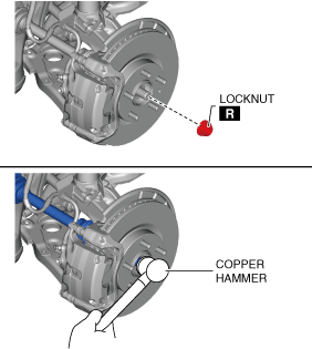
7. Remove the locknut with the brake pedal depressed. (See Locknut Installation Note.)
ac30zw00000472
|
8. Temporarily install a spare nut to the front drive shaft.
9. Tap the nut with a copper hammer and separate the front drive shaft from the axle.
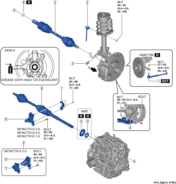
10. Remove in the order shown in the figure.
11. Install in the reverse order of removal.
ac30zw00005201
|
|
1
|
Tie-rod end
|
|
2
|
Front stabilizer control link (upper side)
|
|
3
|
Brake hose clip
|
|
4
|
Front lower arm ball joint
|
|
5
|
Front drive shaft (LH)
|
|
6
|
Front drive shaft clip
|
|
7
|
Bracket No.2
|
|
8
|
Front drive shaft (RH)
|
|
9
|
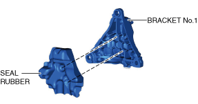
Bracket No.1, Seal rubber component (With seal rubber)
|
|
10
|
Bracket No.1
|
|
11
|
Seal rubber (With seal rubber)
|
|
12
|
Transfer oil seal (RH) No.1
|
|
13
|
Transfer oil seal (RH) No.3
|
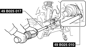
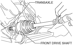
Front Drive Shaft (LH) Removal Note
1. Perform the following procedures to separate the front drive shaft (LH) from the transaxle.
ac8jjw00002591
|
2. Remove the front drive shaft (LH).
Bracket, Front Drive Shaft (RH) Installation Note
1. Install the seal rubber to the bracket No.1 as shown in the figure. (With seal rubber)
ac30zw00003083
|
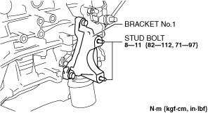
2. Tighten the bracket No.1 stud bolts.
ac30zw00001397
|
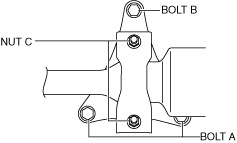
3. Temporarily tighten bolts A and B.
ac30zw00000474
|
4. Completely tighten the bolts in the order of A and B.
5. Apply manual transaxle oil or ATF to the oil seal lip.
6. Insert the front drive shaft into the transaxle until the front drive shaft bearing contacts the bracket No.1 stopper.
7. After temporarily tightening nut C, and completely tighten it.
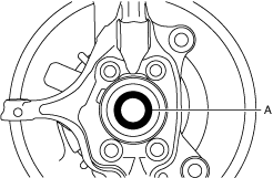
8. Apply grease (D4Y0 33247 or equivalent) to the wheel bearing inner race and front drive shaft contact surfaces (area A in the figure).
am3zzw00034658
|
9. Insert the front drive shaft to the wheel hub.
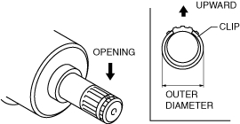
Front Drive Shaft Clip Installation Note
1. Install a new clip to the clip groove at the end of the front drive shaft (LH) with the clip opening facing upward.
am3uuw00006877
|
2. Verify that the outer diameter of the clip is within the standard.
Specification
|
Engine type |
Outer diameter |
|---|---|
|
SKYACTIV-G 2.0 (MTX(2WD))
|
Less than 31.2 mm {1.23 in}
|
|
Except SKYACTIV-G 2.0 (MTX(2WD))
|
Less than 34.0 mm {1.34 in}
|
Front Drive Shaft (LH) Installation Note
1. Apply manual transaxle oil or ATF to the oil seal lip.
2. Apply grease (D4Y0 33247 or equivalent) to the wheel bearing inner race and front drive shaft contact surfaces (area A in the figure).
am3zzw00034658
|
3. Insert the front drive shaft to the wheel hub.
4. Install the front drive shaft to the transaxle.
ac8wzw00002084
|
5. After installation, verify that the front drive shaft is securely held by the clip by pulling the outer ring on the transaxle side towards the axle.
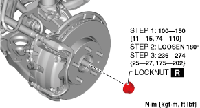
Locknut Installation Note
1. If dust or grease is on the drive shaft thread area, wipe it off with a cloth.
2. Working with two people, one should depress and hold the pedal down.
3. While the brake pedal is depressed, the other should tighten the locknut using the following procedure.
ac30zw00003986
|