• Performing the following procedures could cause an open circuit in the rear ABS wheel-speed sensor wiring harness if it is pulled by mistake. Before servicing, disconnect the rear ABS wheel-speed sensor and set it aside so that the wiring harness will not be pulled by mistake.
• If the characteristic value of a new coupling component is not input to the PCM or the characteristic value is input incorrectly after replacing the coupling component, it could result in the following conditions.
― The system does not operate normally.
― A problem with durability of the coupling component occurs.
• After replacing the coupling component, read out the characteristic value of a new coupling component and write it to the PCM. (See COUPLING COMPONENT CALIBRATION DATA WRITING.)
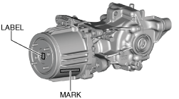
• Read out the characteristic value of the coupling component from the label or mark shown in the figure.
ac30zw00003084
1. Switch the ignition ON (engine off).
2. Release the electric parking brake.
3. Switch the ignition off while pressing the electric parking brake switch.
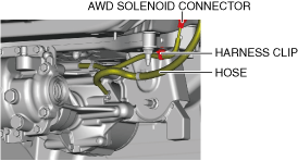
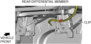
11. Disconnect the AWD solenoid connector and harness clip.
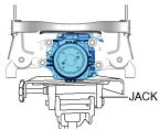
12. Support the rear differential component using a jack.
ac30zw00000478
Warning
• Always verify that the rear differential component is securely supported by a jack. If the rear differential component falls off, it can cause serious injury or death, and damage to the vehicle.
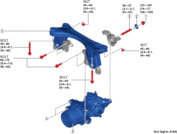
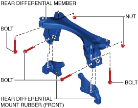
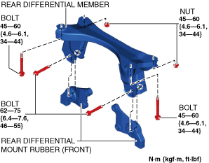
2. Remove the rear differential mount rubber (front).
ac30zw00000481
3. Remove the rear differential member.
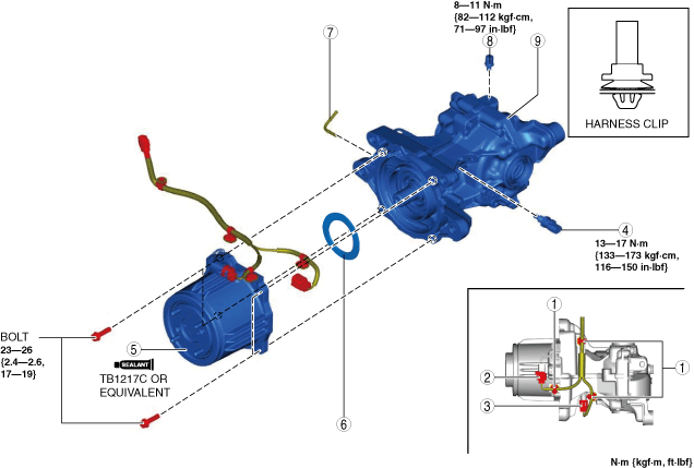
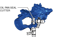
Coupling Component Removal Note
1. Disconnect the coupling component using an oil pan seal cutter.
aaxjjw00026319
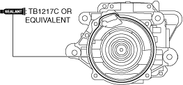
Coupling Component Installation Note
Note
• Clean away the remaining silicone sealant before applying new silicone sealant.
• Install the coupling component before the applied silicone sealant starts to harden.
• Add rear differential oil after the silicone sealant hardens.
1. Apply a thin layer of silicone sealant TB1217C or equivalent to the contact surfaces of the coupling component and the rear differential.
ac30zw00005306
2. Install the coupling component to the differential.
3. After replacing the coupling component, read out the characteristic value of a new coupling component and write it to the PCM. (See COUPLING COMPONENT CALIBRATION DATA WRITING.)
Rear Differential Member Installation Note
1. Install the rear differential member.
ac30zw00000483
2. Install the rear differential mount rubber (front).
3. Assemble the clip.
ac30zw00000480
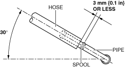
Hose Installation Note
1. Install the hose to the pipe as shown in the figure.
 ac30zw00003084