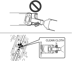
• If the constant velocity joint is bent during propeller shaft removal/installation or transportation after servicing, the constant velocity joint boot may contact the metallic cover and the boot may be damaged. Insert a clean cloth between the boot and the metallic cover before servicing to protect the boot.
ac30zw00004034
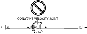
• If excessive force is applied in the axial direction of the constant velocity joint, the internal parts of the constant velocity joint could be damaged. Do not apply excessive force in the axial direction.
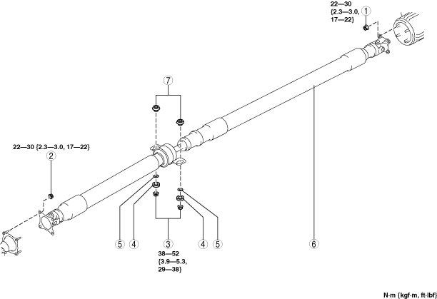
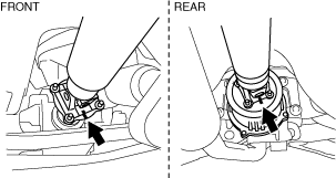
1. Before removing the nut, place alignment marks on the companion flange (front) and constant velocity joint, and on the coupling component (rear) and yoke.
am3zzw00031469
2. Loosen the nuts (front, rear, center bearing support).
3. Remove the front and rear nuts.
Caution
• Propeller shaft is attached to the stud.
4. Press the propeller shaft and remove it from the rear side.
Caution
• Do not bend the propeller shaft to the extent that it interferes with the boot.
5. Remove the center bearing support nut, then remove the propeller shaft.
Propeller Shaft Installation Note
Caution
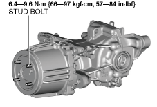
• If the nuts are loosened, verify that the stud bolt tightening torque against the coupling is 6.4 N·m {65 kgf·cm, 57 in·lbf} or more. If the tightening torque is less than 6.4 N·m {65 kgf·cm, 57 in·lbf}, tighten the stud bolt with 6.4—9.6 N·m {66—97 kgf·cm, 57—84 in·lbf}.
aaxjjw00026341
• When loosening the nut, if a nut is stuck to a stud bolt, replace the stud bolt with a new one.
• When replacing the stud bolts, clean off oil and foreign matter on the bolts and coupling installation areas in advance.
Note
• The stud bolts are entirely threaded with no front/rear distinction.
1. Degrease the tightening area.
2. Align the alignment marks, and temporarily install the nuts (front, center bearing support, rear).
am3zzw00031469
Caution
• Do not bend the propeller shaft to the extent that it interferes with the boot.
3. Tighten the nut (front) with specified torque first, and then install the other nuts.