System malfunction location
DTC C0033:07
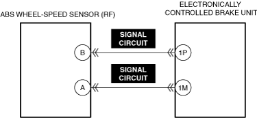
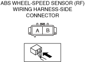
ABS wheel-speed sensor (RF)
DTC C0034:07, C0034:29, C0034:2F, C0034:37 or C0034:64
ABS wheel-speed sensor (RF), ABS wheel-speed sensor rotor
Detection condition
• C0033:07
-
― While driving at a vehicle speed of 14 km/h {8.7 mph} or more, the electronically controlled brake unit detects a periodic pulse deficiency in the signal wave pattern of the ABS wheel-speed sensor (RF).
• C0034:07
-
― The electronically controlled brake unit detects a sudden change in the wheel acceleration on the right front wheel.
• C0034:29
-
― While driving at a vehicle speed of 20 km/h {12 mph} or more, the electronically controlled brake unit detects that the wheel speed signal of the right front wheel is lower than the specification compared to the other wheel speed signals.
• C0034:2F
-
― While driving, the electronically controlled brake unit detects any of the following conditions.
-
• Amount of change in wheel speed of right front wheel is larger than specification• ABS control corresponding to right front wheel continues for 28 s or more
-
• C0034:37
-
― While driving, the electronically controlled brake unit detects that the wheel speed signal of the right front wheel is extremely high.
• C0034:64
-
― While driving at a vehicle speed of 20 km/h {12 mph} or more, the electronically controlled brake unit detects that the wheel speed signal of the right front wheel is higher than the specification compared to the other wheel speed signals.
Fail-safe
Refer to “DTC Table” and “Fail-safe Function Malfunction Contents Table”. (See DTC TABLE [ELECTRONICALLY CONTROLLED BRAKE UNIT].)
Possible cause
• Continuous ABS operation
• ABS wheel-speed sensor (RF) connector or terminals malfunction
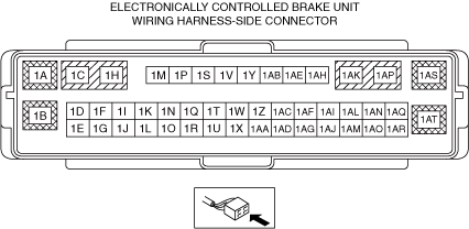
• Electronically controlled brake unit connector or terminals malfunction
• ABS sensor rotor malfunction (missing ABS sensor rotor teeth due to foreign material obstruction)
• ABS wheel-speed sensor (RF) or ABS sensor rotor installation malfunction (If the ABS sensor rotor is installed at an angle, it may cause output of abnormal wave pattern at high speeds.)
• Excessive clearance between the ABS wheel-speed sensor and sensor rotor
• ABS wheel-speed sensor (RF) malfunction
• Electronically controlled brake unit malfunction