ELECTRONICALLY CONTROLLED BRAKE UNIT REMOVAL/INSTALLATION [R.H.D.]
ELECTRONICALLY CONTROLLED BRAKE UNIT REMOVAL/INSTALLATION [R.H.D.]
id0420001002x5
Replacement Part
Brake switch
Quantity: 1
Location of use: Brake pedal
Oil and Chemical Type
Brake fluid type
Type: Mazda Genuine Brake Fluid or equivalent
Warning
• If the initialization of the sensors for the electronically controlled brake unit related parts is not completed, the electronically controlled brake unit will not operate normally which could lead to an unexpected accident. Therefore, if the electronically controlled brake unit is replaced and removed/installed, always perform the initialization of the sensors for the electronically controlled brake unit related parts so that the electronically controlled brake unit will operate normally.
• Always end maintenance mode after performing the servicing in maintenance mode. Otherwise, driving the vehicle without ending maintenance mode could result in an accident.
Caution
• When replacing the electronically controlled brake unit, perform the configuration to assure that the system operates correctly. (See CONFIGURATION.)
• Do not empty the brake fluid in the following brake related parts. Otherwise, the electronically controlled brake unit could be damaged.
― Electronically controlled brake unit
― Brake fluid reserve tank
― Rear brake caliper
• The internal parts of the electronically controlled brake unit could be damaged if dropped. Be careful not to drop the electronically controlled brake unit. Replace the electronically controlled brake unit if it is subjected to an impact.
• Brake fluid will damage painted surfaces. Be careful not to spill any on painted surfaces. In addition, if there is any brake fluid on the wiring harness, the wire insulation may corrode causing a malfunction such as a short circuit. If brake fluid gets on a painted surface or wiring harness, wash and flush it off completely with water immediately.
• Once the brake switch clearance has automatically been adjusted, it cannot be adjusted again. Therefore, replace the switch with a new one when replacing the electronically controlled brake unit or performing any procedure that changes the brake pedal stroke.
• When disconnecting the brake pipe from the electronically controlled brake unit, always plug and seal the electronically controlled brake unit so that brake fluid does not leak.
• A new electronically controlled brake unit has been plugged sealing off brake fluid. For this reason, remove the plug of the electronically controlled brake unit directly before installing it to the vehicle. Other than this, do not remove the plug of the electronically controlled brake unit.
Note
• After replacing the electronically controlled brake unit and performing an operation/release of the electric parking brake, the electronically controlled brake unit performs a check of the related parts, and records the operation/release condition of the electric parking brake.
• Tighten the brake pipe flare nut using any commercially available flare nut wrench.
• When switching to maintenance mode, the electronically controlled brake unit and the electric parking brake functions are canceled.
• When switching to maintenance mode, the clearance between the rear disc pad and the rear disc plate widens.
• When the maintenance mode is ended, the electric parking brake motor gear unit operating time is longer than normal due to the automatic adjustment of the electric parking brake.
• Bleed the air inside the brake fluid reserve tank when the fluid inside the brake fluid reserve tank is empty.
1. To replace the electronically controlled brake unit, perform the following procedure.
(1) Connect the M-MDS to the DLC-2.
(2) Switch the ignition ON (engine off).
(3) Activate the M-MDS and perform the following procedure.
1) Press [Start] to start the vehicle identification.
2) Press the [Toolbox] tab.
3) Press the [Work Support] icon.
4) Press [Configuration].
5) Press [Run] to perform the configuration.
6) Press [DSC].
7) When [Install the new ECU] is displayed, move to the electronically controlled brake unit replacement procedure.
(10) Operate the electric parking brake switch using the following procedure to verify the operation of the electric parking brake and perform the automatic adjustment.
1) Switch the ignition ON (engine off).
2) Operate the electric parking brake.
• If the electric parking brake cannot be operated, release it once and then try to re-operate it.
― If the electric parking brake cannot be operated/released, perform a DTC inspection as a malfunction of the electric parking brake may have occurred. (See DTC INSPECTION.)
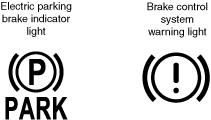
3) Verify that the electric parking brake indicator light turns on and the brake control system warning light turns off.
ac30zw00003455
• If the electric parking brake indicator light does not turn on, the electric parking brake indicator light flashes, or the brake control system warning light does not turn off, perform a DTC inspection as a malfunction of the electric parking brake may have occurred. (See DTC INSPECTION.)
4) Release the electric parking brake.
5) Verify that the electric parking brake indicator light and the brake control system warning light turn off.
• If the electric parking brake indicator light and the brake control system warning light do not turn off, perform a DTC inspection as a malfunction of the electric parking brake may have occurred. (See DTC INSPECTION.)
• If sand or other particles get into the connector, it may be difficult to remove. To prevent damaging the connector, be careful not to use excessive force when disconnecting it.
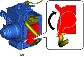
1. Pull the lock lever up in the direction of the arrow while pressing the tab of the lock lever.
am3zzw00034304
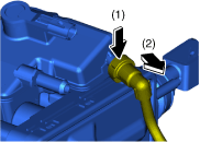
Clutch Reserve Hose Removal Note (MTX)
1. Disconnect the clutch reserve hose in the order shown in the figure.
am3zzw00034305
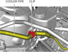
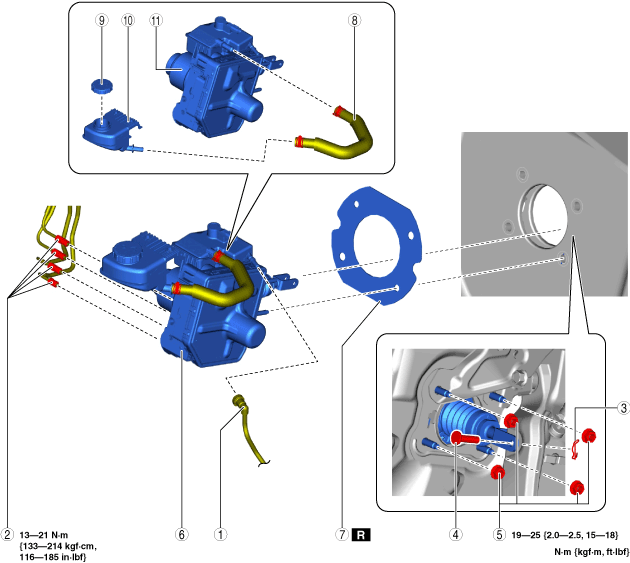
Brake Pipe Removal Note
1. Place an alignment mark on the brake pipe and electronically controlled brake unit.
am3zzw00034306
2. Apply protective tape to the connector to prevent brake fluid from entering.
3. Disconnect the brake pipes.
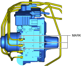
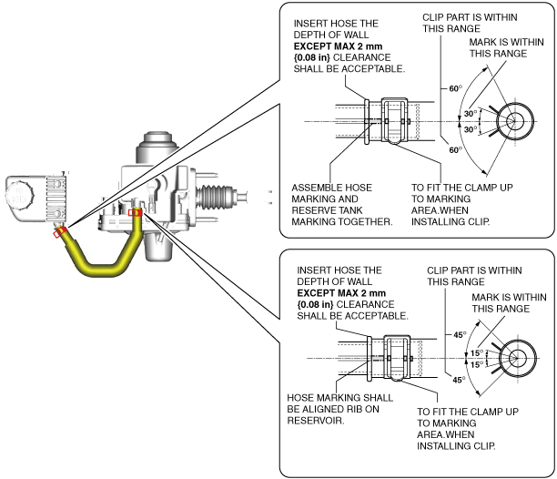
Reserve Hose Installation Note
1. Install the reserve hoses as shown in the figure.
ac30zw00002532
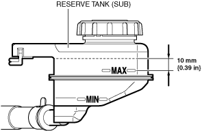
Electronically Controlled Brake Unit Component Installation Note
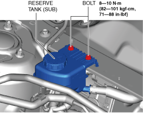
1. Add brake fluid up to approx. 10 mm {0.39 in} above the MAX line of the reserve tank (sub).
am3zzw00034308
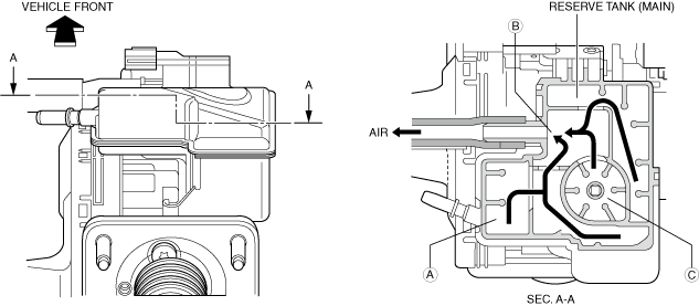
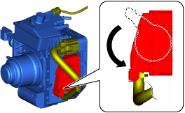
2. Guide the air in clutch area A in the reserve tank (main) to connection port B while tilting the electronically controlled brake unit.
3. Guide the air in float area C in the reserve tank (main) to connection port B while tilting the electronically controlled brake unit.
am3zzw00034309
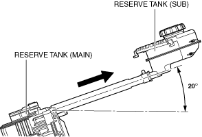
4. Tilt the hose between the electronically controlled brake unit and the reserve tank (sub) as shown in the figure.
am3zzw00034310
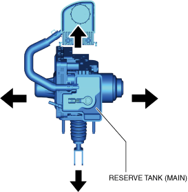
5. Tilt the electronically controlled brake unit in each direction shown in the figure and verify that there is no air on the fluid surface in the reserve tank (main).
ac30zw00005310
6. Align the brake fluid in the reserve tank (sub) with the MAX line and install it to the vehicle.
Note
• After installing the electronically controlled brake unit, if the brake fluid in the reserve tank (sub) is higher than the MAX line, there is air in the brake fluid.Repeat from Step 1 to Step 5.
Brake Pipe Installation Note
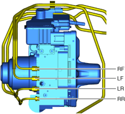
1. Align the marks made before removal and install the brake pipe to the electronically controlled brake unit and brake pipe joint referring to the figure.
am3zzw00034312
2. Tighten the brake pipe to the specified torque using the commercially available flare nut wrench.
Clutch Reserve Hose Installation Note (MTX)
1. Insert the clutch reserve hose into the reserve tank (main).
2. Pull the clutch reserve hose to verify that it does not come off, and reinsert it completely.
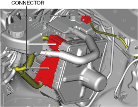
Connector Installation Note
1. Connect the connector and pull the lock lever down in the direction of the arrow.
am3zzw00034313
2. After connecting the connector, verify that the connector cover is completely pushed in.