|
1
|
VERIFY OPERATION CONDITION BY CUSTOMER
• Ask the customer if they have repeatedly pulled up/pressed down the electric parking brake switch quickly for a short period.
• Has the customer repeatedly pulled up/pressed down the electric parking brake switch quickly for a short period?
|
Yes
|
The system is normal. (Explain to the customer that repeatedly pulling up/pressing down the electric parking brake switch quickly for a short period was the cause of the DTC being displayed, and explain how to appropriately operate the switch.)
|
|
No
|
Go to the next step.
|
|
2
|
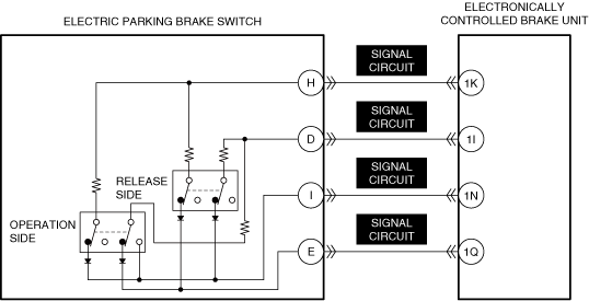
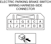
INSPECT ELECTRIC PARKING BRAKE SWITCH CONNECTOR FOR MALFUNCTION
• Inspect the applicable connector and terminal.
• Are the connector and terminal normal?
|
Yes
|
Go to the next step.
|
|
No
|
Repair or replace the malfunctioning location and perform the repair completion verification.
|
|
3
|
INSPECT ELECTRIC PARKING BRAKE SWITCH FOR MALFUNCTION
• Inspect the applicable part.
• Is the part normal?
|
Yes
|
Go to the next step.
|
|
No
|
Repair or replace the malfunctioning location and perform the repair completion verification.
|
|
4
|
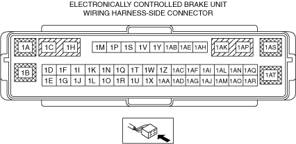
INSPECT ELECTRONICALLY CONTROLLED BRAKE UNIT CONNECTOR FOR MALFUNCTION
• Inspect the applicable connector and terminal.
• Are the connector and terminal normal?
|
Yes
|
Go to the next step.
|
|
No
|
Repair or replace the malfunctioning location and perform the repair completion verification.
|
|
5
|
INSPECT ELECTRIC PARKING BRAKE SWITCH SIGNAL CIRCUIT FOR SHORT TO GROUND
• Inspect the applicable circuit for a short to ground.
• Is the circuit normal?
|
Yes
|
Go to the next step.
|
|
No
|
Repair or replace the malfunctioning location and perform the repair completion verification.
|
|
6
|
INSPECT ELECTRIC PARKING BRAKE SWITCH SIGNAL CIRCUIT FOR SHORT TO POWER SUPPLY
• Inspect the applicable circuit for a short to power supply.
• Is the circuit normal?
|
Yes
|
Go to the next step.
|
|
No
|
Repair or replace the malfunctioning location and perform the repair completion verification.
|
|
7
|
INSPECT ELECTRIC PARKING BRAKE SWITCH SIGNAL CIRCUIT FOR OPEN CIRCUIT
• Inspect the applicable circuit for open circuit.
• Is the circuit normal?
|
Yes
|
Go to the next step.
|
|
No
|
Repair or replace the malfunctioning location and perform the repair completion verification.
|
|
8
|
INSPECT ELECTRIC PARKING BRAKE SWITCH SIGNAL CIRCUITS FOR SHORT CIRCUIT
• Inspect the applicable circuits for short circuit.
• Is the circuit normal?
|
Yes
|
Go to the next step.
|
|
No
|
Repair or replace the malfunctioning location and perform the repair completion verification.
|
|
Repair completion verification 1
|
VERIFY THAT VEHICLE IS REPAIRED
• Install/connect the part removed/disconnected during the troubleshooting procedure.
• Clear the DTC recorded in the memory.
• Perform the following procedure 3 times or more.
-
― Pull up the electric parking brake switch to operate the electric parking brake.
― Press down the electric parking brake switch to release the electric parking brake.
• Perform the DTC inspection for the electronically controlled brake unit.
• Is the same Pending DTC present?
|
Yes
|
Refer to the controller area network (CAN) malfunction diagnosis flow to inspect for a CAN communication error.
If the CAN communication is normal, perform the diagnosis from Step 1.
• If the malfunction recurs, replace the electronically controlled brake unit, then go to the next step.
|
|
No
|
Go to the next step.
|
|
Repair completion verification 2
|
VERIFY IF OTHER DTCs DISPLAYED
• Perform the DTC inspection.
• Are any DTCs displayed?
|
Yes
|
Repair the malfunctioning location according to the applicable DTC troubleshooting.
|
|
No
|
DTC troubleshooting completed.
|