|
1
|
DETERMINE MALFUNCTIONING LOCATION
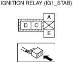
• Switch the ignition ON (engine off or on).
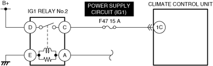
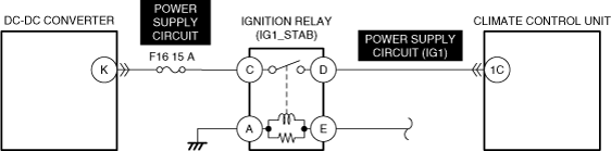
• Measure the voltage at the ignition relay (IG1_STAB) terminal D (wiring harness-side).
• Is the voltage B+?
|
Yes
|
Go to Step 8.
|
|
No
|
Go to the next step.
|
|
2
|
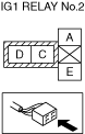
INSPECT IGNITION RELAY (IG1_STAB) FOR MALFUNCTION
• Inspect the applicable part.
• Is the part normal?
|
Yes
|
Go to the next step.
|
|
No
|
Repair or replace the malfunctioning location and perform the repair completion verification.
|
|
3
|
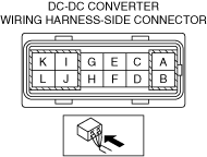
INSPECT DC-DC CONVERTER CONNECTOR FOR MALFUNCTION
• Inspect the applicable connector and terminal.
• Are the connector and terminal normal?
|
Yes
|
Go to the next step.
|
|
No
|
Repair or replace the malfunctioning location and perform the repair completion verification.
|
|
4
|
INSPECT F16 15 A FUSE
• Remove the F16 15 A fuse.
• Inspect the F16 15 A fuse.
• Is the fuse normal?
|
Yes
|
Reinstall the F16 15 A fuse, then go to the next step.
|
|
No
|
Replace the F16 15 A fuse and perform the repair completion verification.
|
|
5
|
INSPECT IGNITION RELAY (IG1_STAB) POWER SUPPLY CIRCUIT FOR SHORT TO GROUND
• Inspect the applicable circuit for a short to ground.
• Is the circuit normal?
|
Yes
|
Go to the next step.
|
|
No
|
Repair or replace the malfunctioning location and perform the repair completion verification.
|
|
6
|
INSPECT IGNITION RELAY (IG1_STAB) POWER SUPPLY CIRCUIT FOR OPEN CIRCUIT
• Inspect the applicable circuit for open circuit.
• Is the circuit normal?
|
Yes
|
Go to the next step.
|
|
No
|
Repair or replace the malfunctioning location and perform the repair completion verification.
|
|
7
|
INSPECT DC-DC CONVERTER FOR MALFUNCTION
• Inspect the applicable part.
• Is the part normal?
|
Yes
|
Go to the next step.
|
|
No
|
Repair or replace the malfunctioning location and perform the repair completion verification.
|
|
8
|
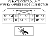
INSPECT CLIMATE CONTROL UNIT CONNECTOR FOR MALFUNCTION
• Inspect the applicable connector and terminal.
• Are the connector and terminal normal?
|
Yes
|
Go to the next step.
|
|
No
|
Repair or replace the malfunctioning location and perform the repair completion verification.
|
|
9
|
INSPECT CLIMATE CONTROL UNIT POWER SUPPLY CIRCUIT (IG1) FOR SHORT TO GROUND
• Inspect the applicable circuit for a short to ground.
• Is the circuit normal?
|
Yes
|
Go to the next step.
|
|
No
|
Repair or replace the malfunctioning location and perform the repair completion verification.
|
|
10
|
INSPECT CLIMATE CONTROL UNIT POWER SUPPLY CIRCUIT (IG1) FOR OPEN CIRCUIT
• Inspect the applicable circuit for open circuit.
• Is the circuit normal?
|
Yes
|
Go to the next step.
|
|
No
|
Repair or replace the malfunctioning location and perform the repair completion verification.
|
|
11
|
INSPECT CLIMATE CONTROL UNIT FOR MALFUNCTION DEPENDING ON REPEATABILITY
• Install/connect the part removed/disconnected during the troubleshooting procedure.
• Clear the DTC recorded in the memory.
• Perform the DTC inspection for the dash-electrical supply unit.
• Is the same Pending DTC present?
|
Yes
|
Refer to the controller area network (CAN) malfunction diagnosis flow to inspect for a CAN communication error.
If the CAN communication is normal, replace the malfunctioning location and perform the repair completion verification.
|
|
No
|
Go to repair completion verification 2.
|
|
Repair completion verification 1
|
VERIFY THAT VEHICLE IS REPAIRED
• Install/connect the part removed/disconnected during the troubleshooting procedure.
• Clear the DTC recorded in the memory.
• Perform the DTC inspection for the dash-electrical supply unit.
• Is the same Pending DTC present?
|
Yes
|
Refer to the controller area network (CAN) malfunction diagnosis flow to inspect for a CAN communication error.
If the CAN communication is normal, perform the diagnosis from Step 1.
• If the malfunction recurs, replace the dash-electrical supply unit, then go to the next step.
|
|
No
|
Go to the next step.
|
|
Repair completion verification 2
|
VERIFY IF OTHER DTCs DISPLAYED
• Perform the DTC inspection.
• Are any DTCs displayed?
|
Yes
|
Repair the malfunctioning location according to the applicable DTC troubleshooting.
|
|
No
|
DTC troubleshooting completed.
|