|
1
|
VERIFY BODY CONTROL MODULE (BCM) DTCs AGAIN
• Clear the DTC recorded in the memory.
• Perform the DTC inspection for the body control module (BCM).
• Is the same Pending DTC present?
|
Yes
|
Go to the next step.
|
|
No
|
Go to repair completion verification 2.
|
|
2
|
INSPECT Mazda EMERGENCY ASSISTANCE CONTROL MODULE FOR MALFUNCTION
• Perform the DTC inspection for the Mazda EMERGENCY ASSISTANCE control module.
• Is a DTC displayed?
|
Yes
|
Repair the malfunctioning location according to the applicable DTC troubleshooting.
|
|
No
|
Go to the next step.
|
|
3
|
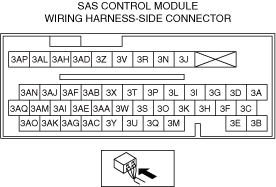
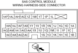
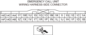
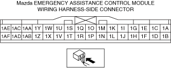
INSPECT Mazda EMERGENCY ASSISTANCE CONTROL MODULE CONNECTOR FOR MALFUNCTION
• Inspect the applicable connector and terminal.
• Are the connector and terminal normal?
|
Yes
|
Go to the next step.
|
|
No
|
Repair or replace the malfunctioning location and perform the repair completion verification.
|
|
4
|
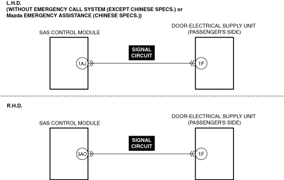
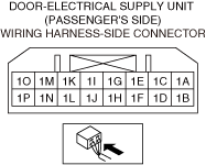
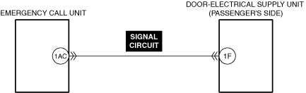
INSPECT DOOR-ELECTRICAL SUPPLY UNIT (PASSENGER’S SIDE) CONNECTOR FOR MALFUNCTION
• Inspect the applicable connector and terminal.
• Are the connector and terminal normal?
|
Yes
|
Go to the next step.
|
|
No
|
Repair or replace the malfunctioning location and perform the repair completion verification.
|
|
5
|
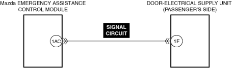
INSPECT Mazda EMERGENCY ASSISTANCE CONTROL MODULE SIGNAL CIRCUIT FOR SHORT TO GROUND
• Inspect the applicable circuit for a short to ground.
• Is the circuit normal?
|
Yes
|
Go to the next step.
|
|
No
|
Repair or replace the malfunctioning location and perform the repair completion verification.
|
|
6
|
INSPECT Mazda EMERGENCY ASSISTANCE CONTROL MODULE SIGNAL CIRCUIT FOR OPEN CIRCUIT
• Inspect the applicable circuit for an open circuit.
• Is the circuit normal?
|
Yes
|
Go to the next step.
|
|
No
|
Repair or replace the malfunctioning location and perform the repair completion verification.
|
|
7
|
INSPECT Mazda EMERGENCY ASSISTANCE CONTROL MODULE FOR MALFUNCTION DEPENDING ON REPEATABILITY
• Install/connect the part removed/disconnected during the troubleshooting procedure.
• Clear the DTC recorded in the memory.
• Perform the DTC inspection for the body control module (BCM).
• Is the same Pending DTC present?
|
Yes
|
Refer to the controller area network (CAN) malfunction diagnosis flow to inspect for a CAN communication error.
If the CAN communication is normal, replace the Mazda EMERGENCY ASSISTANCE control module and perform the repair completion verification.
|
|
No
|
Go to repair completion verification 2.
|
|
8
|
INSPECT DOOR-ELECTRICAL SUPPLY UNIT (PASSENGER’S SIDE) FOR MALFUNCTION DEPENDING ON REPEATABILITY
• Install/connect the part removed/disconnected during the troubleshooting procedure.
• Clear the DTC recorded in the memory.
• Perform the DTC inspection for the body control module (BCM).
• Is the same Pending DTC present?
|
Yes
|
Refer to the controller area network (CAN) malfunction diagnosis flow to inspect for a CAN communication error.
If the CAN communication is normal, replace the door-electrical supply unit (passenger’s side) and perform the repair completion verification.
|
|
No
|
Go to repair completion verification 2.
|
|
Repair completion verification 1
|
VERIFY THAT VEHICLE IS REPAIRED
• Install/connect the part removed/disconnected during the troubleshooting procedure.
• Clear the DTC recorded in the memory.
• Perform the DTC inspection for the body control module (BCM).
• Is the same Pending DTC present?
|
Yes
|
Refer to the controller area network (CAN) malfunction diagnosis flow to inspect for a CAN communication error.
If the CAN communication is normal, perform the diagnosis from Step 1.
• If the malfunction recurs, replace the body control module (BCM), then go to the next step.
|
|
No
|
Go to the next step.
|
|
Repair completion verification 2
|
VERIFY IF OTHER DTC IS DISPLAYED
• Perform the DTC inspection.
• Are any other DTCs displayed?
|
Yes
|
Repair the malfunctioning location according to the applicable DTC troubleshooting.
|
|
No
|
DTC troubleshooting completed.
|