1. Remove the under cover.
2. Remove the splash shield.
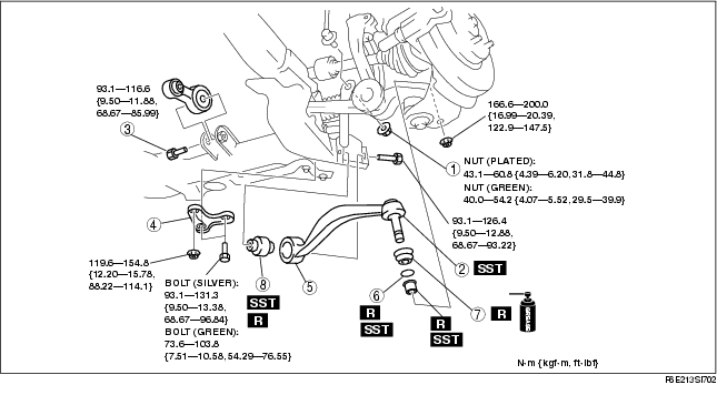
3. Remove the steering gear and linkage installation bolts, and pipe component installation bolts from the front crossmember, then suspend the steering gear and linkage with a cable.
Tightening torque4. Remove in the order indicated in the table.
5. Install in the reverse order of removal.
6. Inspect the front wheel alignment. (See FRONT WHEEL ALIGNMENT.)
.
|
1
|
Nut (stabillizer control link lower side)
|
|
2
|
Front lower arm (rear) ball joint
|
|
3
|
No.1 engine mount center bolt
|
|
4
|
Crossmember bracket
|
|
5
|
Front lower arm (rear)
|
|
6
|
Clip
(See Clip Installation Note.)
|
|
7
|
Dust boot
|
|
8
|
Front lower arm (rear) bushing
|
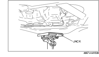
1. Support the crossmember component with a jack and remove the nuts.
2. Remove the crossmember bracket.
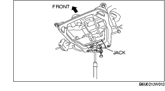
1. Support the front crossmember with a jack.
2. Loosen the front crossmember installation bolts (front side).
3. Remove the front crossmember installation bolts (rear side).
4. Remove the front lower arm (rear) bolt, while lowering the front crossmember slowly.
5. Remove the front lower arm (rear).
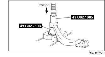
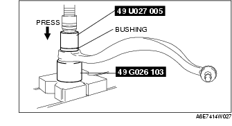
1. Press the bushing out using the SSTs.
2. Remove the front lower arm (rear) from the press and tap the bushing out with a hammer.
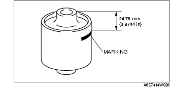
1. Mark the new bushing as shown in the figure.
2. Press the bushing in to the marking using the SSTs.
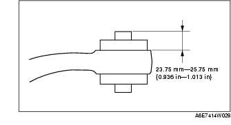
3. Verify that clearance distance A-B is 23.75 mm-25.75 mm {0.936 in-1.013 in}.
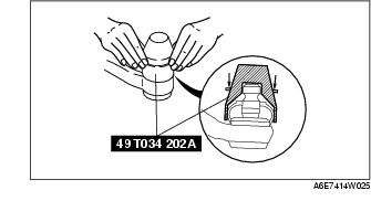
1. Wipe the grease off the ball stud.
2. Fill the inside of the new dust boot with grease.
3. Install the boot on the ball joint.
4. Install the new clip using the SST.
5. Verify that the clip is installed securely to the groove.
6. Wipe away the excess grease.
1. Install the lower arm (rear) so that identification mark (L or R) faces toward the front of the vehicle.