MANUAL TRANSAXLE REMOVAL/INSTALLATION [A26MX-R]
MANUAL TRANSAXLE REMOVAL/INSTALLATION [A26MX-R]
id051521800600
1. Remove the transfer. (See TRANSFER REMOVAL/INSTALLATION [A26MX-R])
2. Disconnect the negative battery cable.
3. Remove the air cleaner. (See INTAKE AIR SYSTEM REMOVAL/INSTALLATION [L3 Turbo])
4. Remove the charge air cooler. (See INTAKE AIR SYSTEM REMOVAL/INSTALLATION [L3 Turbo])
5. Disconnect the reverse switch and neutral switch connector.
6. Remove the starter. (See STARTER REMOVAL/INSTALLATION [L3 Turbo])
-
Caution
-
• The A/C compressor could be damaged by interference with the body frame when removing the transaxle. When removing the transaxle, set the A/C compressor in a location out of the way.
7. Set the A/C compressor out of the way to prevent interference with the body frame.
-
(1) Remove the drive belt. (See DRIVE BELT REPLACEMENT [L3 Turbo].)
-
(2) Remove the A/C compressor from the engine with the pipe connected. (See A/C COMPRESSOR REMOVAL/INSTALLATION [L8, LF, L3, L3 Turbo].)
-
(3) Secure the A/C compressor with a cord or similar object to prevent it from falling.
8. Drain the transaxle oil into a suitable container.
-
Warning
-
• Improperly jacking a transaxle is dangerous. It can slip off the jack and may cause serious injury.
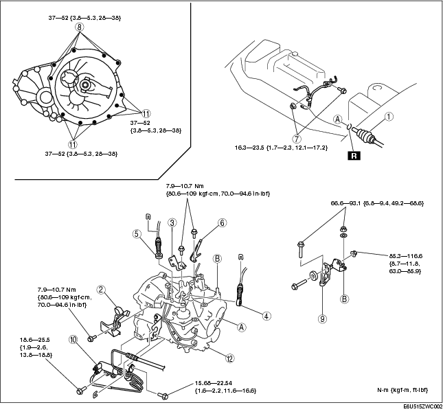
9. Remove in the order indicated in the figure.
10. Install in the reverse order of removal.
11. Add the specified amount of specified transaxle oil. (See TRANSAXLE OIL REPLACEMENT [A26MX-R].)
12. Warm up the engine and transaxle, inspect for oil leakage, and inspect the transaxle operation.
.
|
1
|
Drive shaft
|
|
2
|
Engine wiring harness bracket
|
|
3
|
Connector bracket
|
|
4
|
Selector cable
|
|
5
|
Shift cable
|
|
6
|
Wiring harness bracket
|
|
7
|
Water pipe installation bolt and nut
|
|
8
|
Transaxle mounting bolt (upper side)
|
|
9
|
No.4 engine mount bracket
|
|
10
|
Clutch release cylinder
|
|
11
|
Transaxle mounting bolt (lower side)
|
|
12
|
Manual transaxle
|
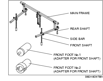
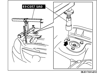
No.4 Engine Mount Bracket Removal Note
1. Install the SST using the following procedure.
-
Caution
-
• Refer to the SST instruction manual for the basic handing procedure.
-
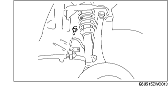
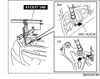
(1) Install the right rear shaft of the SST to the bolt of the right shock absorber as shown in the figure.
-
(2) Install the left rear shaft of the SST to the bolt of the left shock absorber. (Identical position to the right side)
-
Caution
-
• When setting the SST on the right side, make sure it doesn't interfere with the DSC HU/CM.
-
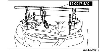
(3) Install the left/right front shaft of the SST with front foot No.2 to the bolt as shown in the figure.
-
(4) Adjust the positions of the SST side bars so that they are the same height (left and right) and horizontal.
-
(5) Make sure each joint is securely tightened.
2. Support the engine using the SST.
-
Note
-
• The SST (49 E017 5A0) can be used in place of the SST (49 C017 5A0).
3. Remove the No.4 engine mount bracket.
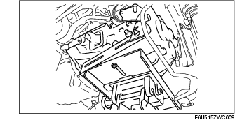
Manual Transaxle Removal Note
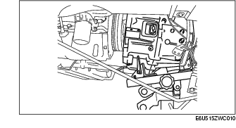
1. Loosen the bolt shown in the figure and set the brake pipe out of the way.
2. Lean the engine toward the transaxle.
3. Support the transaxle on a jack.
4. Remove the transaxle mounting bolts.
5. Remove the transaxle.
Manual Transaxle Installation Note
1. Set the transaxle on a jack and lift into place.
2. Install the transaxle mounting bolts.
3. Tighten the bolt shown in the figure.
Tightening torque
-
18.5-25.5 N·m {1.89-2.60 kgf·m, 13.7-18.8 ft·lbf}
No.4 Engine Mount Bracket Installation Note
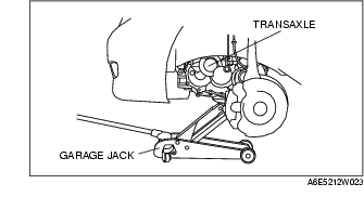
1. Set the transaxle on a garage jack and lift it.
2. Verify that the engine mount rubber is installed as shown.
3. By aligning the holes with the stud bolts, install the No.4 engine mount bracket to the transaxle.
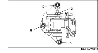
4. Align the hole of the No.4 engine mount bracket with the No.4 engine mount rubber on vehicle, and temporarily tighten nut D.
5. Lightly tighten nuts B, C and bolt A.
6. Tighten nuts B, C in order of B→C, then bolt A.
7. Tighten nut D.
Tightening torque
-
A, B, C: 66.6-93.1 N·m
-
{6.8-9.4 kgf·m, 49.2-68.6 ft·lbf}
-
D: 85.3-116.6 N·m
-
{8.7-11.8 kgf·m, 62.9-85.9 ft·lbf}
8. Remove the garage jack.
9. Remove the SST (49 C017 5A0).