 |
am6zzw00014370
DTC P0234:00 [PCM (SKYACTIV-D)]
id0102t5148400
Details On DTCs
|
Description |
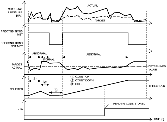
Small-type turbocharger area control system: Overboost |
|
|---|---|---|
|
Detection condition
|
Determination condition
|
• As the result of comparing the actual boost pressure with the target boost pressure, the actual boost pressure exceeds the specification higher than the target boost pressure for a continuous 7 s.
|
|
Preconditions
|
• All of the following conditions are met when diesel particulate filter regeneration control is stopped during boost control feedback
|
|
|
Drive cycle
|
• 2
|
|
|
Self-test type
|
• CMDTC self test
|
|
|
Sensor/unit used
|
• MAP sensor
|
|
|
Fail-safe
|
• Not applicable
|
|
|
Vehicle status when dtcs are output
|
• Not applicable
|
|
|
Possible cause
|
• PCM input signal error
• Turbocharger solenoid valve malfunction
• Actuator position sensor (turbocharger with variable turbine geometry) malfunction
• Turbocharger actuator malfunction
• Turbocharger malfunction
• PCM malfunction
|
|
System Wiring Diagram
Function Explanation (DTC Detection Outline)
am6zzw00014370
|
Repeatability Verification Procedure
PID Item/Simulation Item Used In Diagnosis
PID/DATA monitor item table
|
Item (definition) |
Reference |
|---|---|
|
MAP
|
|
|
MAP_DSD
|
|
|
TURBO_POS_ACT
|
Simulation item
|
Item (definition) |
Reference |
|---|---|
|
TURBO_POS_DSD
|
• (See SIMULATION TABLE [PCM (SKYACTIV-D)].)
|
Function Inspection Using M-MDS
|
Step |
Inspection |
Results |
Action |
|---|---|---|---|
|
1
|
PURPOSE: VERIFY RELATED REPAIR INFORMATION OR SERVICE INFORMATION AVAILABILITY
• Verify related Service Bulletins, on-line repair information, or Service Information availability.
• Is any related Information available?
|
Yes
|
Perform repair or diagnosis according to the available information.
• If the vehicle is not repaired, go to the next step.
|
|
No
|
Go to the next step.
|
||
|
2
|
PURPOSE: VERIFY DTC CAUSING FREEZE FRAME DATA
• Is DTC P0234:00 causing the freeze frame data?
|
Yes
|
Go to the next step.
|
|
No
|
Inspect the DTC causing the freeze frame data.
(See DTC TABLE [PCM (SKYACTIV-D)].)
|
||
|
3
|
PURPOSE: RECORD VEHICLE STATUS WHEN DTC WAS DETECTED TO UTILIZE WITH REPEATABILITY VERIFICATION
• Record the freeze frame data/snapshot data.
|
—
|
Go to the next step.
|
|
4
|
PURPOSE: VERIFY OTHER RELATED DTCs
• Switch the ignition OFF, and then switch it ON (engine off).
• Display the DTCs using the M-MDS.
(See DTC INSPECTION.)
• Has any DTC other than P0234:00 been stored?
|
Yes
|
Repair the malfunctioning location according to the applicable DTC troubleshooting.
(See DTC TABLE [PCM (SKYACTIV-D)].)
|
|
No
|
Go to the next step.
|
||
|
5
|
PURPOSE: VERIFY MAP SENSOR INPUT SIGNAL
• Start the engine and warm it up.
• Display the following PIDs using the M-MDS.
(See DTC INSPECTION.)
• Are the monitoring values normal?
|
Yes
|
Go to Troubleshooting Diagnostic Procedure to perform the procedure from step 1.
|
|
No
|
Go to the next step.
|
||
|
6
|
PURPOSE: INSPECT WIRING HARNESSES AND CONNECTORS FOR RELATED-SENSOR
• Display the following PIDs using the M-MDS.
(See DTC INSPECTION.)
• When the PCM and MAP sensor connector are shaken, does the PID value include a PID item which has changed?
|
Yes
|
Inspect the related wiring harnesses and connectors.
• Repair or replace the malfunctioning location.
Go to the troubleshooting procedure to perform the procedure from repair completion verification.
|
|
No
|
Go to Troubleshooting Diagnostic Procedure to perform the procedure from step 1.
|
||
|
7
|
PURPOSE: DETERMINE IF MALFUNCTION IS CAUSED BY ACTUATOR POSITION SENSOR MALFUNCTION
• Inspect the actuator position sensor.
• Is the actuator position sensor normal?
|
Yes
|
Go to Troubleshooting Diagnostic Procedure to perform the procedure from step 1.
|
|
No
|
Inspect the related wiring harnesses and connectors.
• Repair or replace the malfunctioning location.
Go to the troubleshooting procedure to perform the procedure from repair completion verification.
|
||
|
8
|
PURPOSE: DETERMINE IF MALFUNCTION IS CAUSED BY VARIABLE TURBINE GEOMETRY TURBOCHARGER ACTUATOR POSITION SENSOR MALFUNCTION
• Inspect the variable turbine geometry turbocharger actuator position sensor.
• Is the variable turbine geometry turbocharger actuator position sensor normal?
|
Yes
|
Go to Troubleshooting Diagnostic Procedure to perform the procedure from step 1.
|
|
No
|
Inspect the related wiring harnesses and connectors.
• Repair or replace the malfunctioning location.
Go to the troubleshooting procedure to perform the procedure from repair completion verification.
|
Troubleshooting Diagnostic Procedure
|
Step |
Inspection |
Results |
Action |
|---|---|---|---|
|
1
|
PURPOSE: INSPECT TURBOCHARGER SOLENOID VALVE FOR MALFUNCTION
• Inspect the applicable part.
• Is the part normal?
|
Yes
|
Go to the next step.
|
|
No
|
Repair or replace the malfunctioning location and perform the repair completion verification.
|
||
|
2
|
INSPECT VARIABLE TURBINE GEOMETRY TURBOCHARGER ACTUATOR FOR MALFUNCTION
• Inspect the applicable part.
• Is the part normal?
|
Yes
|
Go to the next step.
|
|
No
|
Repair or replace the malfunctioning location and perform the repair completion verification.
|
||
|
Repair completion verification 1
|
PURPOSE: VERIFY THAT VEHICLE IS REPAIRED
• Install/connect the part removed/disconnected during the troubleshooting procedure.
• Clear the DTC recorded in the memory.
(See CLEARING DTC.)
• Replicate the vehicle conditions at the time the DTC was detected using the following procedure.
• Perform the DTC inspection for the PCM.
(See DTC INSPECTION.)
• Is the same Pending DTC present?
|
Yes
|
Refer to the controller area network (CAN) malfunction diagnosis flow to inspect for a CAN communication error.
If the CAN communication is normal, perform the diagnosis from Step 1.
• If the malfunction recurs, replace the PCM, then go to the next step.
|
|
No
|
Go to the next step.
|
||
|
Repair completion verification 2
|
PURPOSE: VERIFY IF OTHER DTCs DISPLAYED
• Perform the DTC inspection.
(See DTC INSPECTION.)
• Are any other DTCs displayed?
|
Yes
|
Repair the malfunctioning location according to the applicable DTC troubleshooting.
|
|
No
|
DTC troubleshooting completed.
|