DTC P2204:00 [PCM (SKYACTIV-D)]
id0102t5726000
Details On DTCs
|
Description |
Continuous monitoring of NOx sensor signal validity |
|
|---|---|---|
|
Detection condition
|
Determination conditions
|
• The PCM detects two times that the speed of the signal received from NOx sensor is slower than the target vehicle speed.
|
|
Preconditions
|
• Target heat amount of NOx sensor: 700—1270 kJ
• Battery voltage: 10.9—16.0 V
• exhaust gas temperature sensor No.4: -3549.94—849.96 °C {-6357.89—1561.9 °F}
• CAN communication is normal at engine start for a continuous 20 s or more
• Fuel injection amount: -0.4—11.2 mg/stroke
• Air/fuel ratio of NOx sensor: 1.3
• The following DTCs are not detected:
|
|
|
Drive cycle
|
• 1
|
|
|
Self test type
|
• CMDTC self test
|
|
|
Sensor used
|
• NOx sensor
|
|
|
Fail-safe
|
• Restricts the maximum remaining distance to empty.
|
|
|
Vehicle status when dtcs are output
|
• Not applicable
|
|
|
Possible cause
|
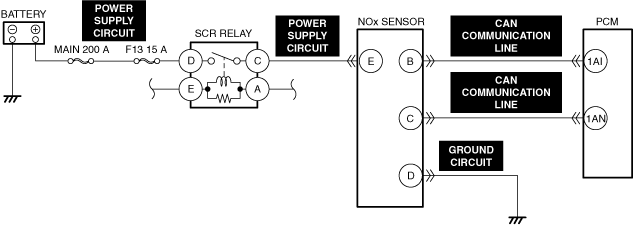
• NOx sensor connector or terminals malfunction
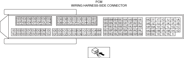
• PCM connector or terminals malfunction
• Exhaust gas temperature sensor No.4 malfunction
• Short to ground or open circuit in SCR RELAY power supply circuit
• MAIN 200 A fuse and/or F13 15 A fuse malfunction
• Short to ground in NOx sensor power supply circuit
• Open circuit in NOx sensor power supply circuit
• Open circuit in any of the following NOx sensor circuits.
• NOx sensor malfunction
• PCM malfunction
|
|
System Wiring Diagram
|
|
|
|
|
|
Function Explanation (DTC Detection Outline)
Repeatability Verification Procedure
1. Perform the "COMPULSORY DIESEL PARTICULATE FILTER REGENERATION". (See COMPULSORY DIESEL PARTICULATE FILTER REGENERATION [SKYACTIV-D 1.8].)
2. Idle the engine for 3 min.
PID Item/Simulation Item Used In Diagnosis
Function Inspection Using M-MDS
|
Step |
Inspection |
Results |
Action |
|---|---|---|---|
|
1
|
PURPOSE: VERIFY RELATED REPAIR INFORMATION OR SERVICE INFORMATION AVAILABILITY
• Verify related Service Bulletins, on-line repair information, or Service Information availability.
• Is any related Information available?
|
Yes
|
Perform repair or diagnosis according to the available information.
• If the vehicle is not repaired, go to the next step.
|
|
No
|
Go to the next step.
|
||
|
2
|
PURPOSE: INSPECT FOR OTHER RELATED DTCs
• Perform the DTC inspection for the PCM.
(See DTC INSPECTION.)
• Are any of the following DTCs displayed?
|
Yes
|
Repair the malfunctioning location according to the applicable DTC troubleshooting.
|
|
No
|
Go to the next step.
|
||
|
3
|
PURPOSE: RECORD VEHICLE STATUS WHEN DTC WAS DETECTED TO UTILIZE WITH REPEATABILITY VERIFICATION
• Record the freeze frame data/snapshot data.
|
—
|
Go to Troubleshooting Diagnostic Procedure to perform the procedure from Step 1.
|
Troubleshooting Diagnostic Procedure
|
Step |
Inspection |
Results |
Action |
|---|---|---|---|
|
1
|
PURPOSE: INSPECT EXHAUST GAS TEMPERATURE SENSOR No.4 FOR MALFUNCTION
• Inspect the applicable part.
• Is the part normal?
|
Yes
|
Go to the next step.
|
|
No
|
Repair or replace the malfunctioning location and perform the repair completion verification.
|
||
|
2
|
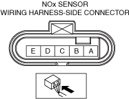
PURPOSE: INSPECT NOx SENSOR CONNECTOR FOR MALFUNCTION
• Inspect the applicable connector and terminal.
(See CONNECTOR INSPECTION.)
• Are the connector and terminal normal?
|
Yes
|
Go to the next step.
|
|
No
|
Repair or replace the malfunctioning location and perform the repair completion verification.
|
||
|
3
|
PURPOSE: INSPECT NOx SENSOR FOR MALFUNCTION
• Inspect the applicable part.
• Is the part normal?
|
Yes
|
Go to the next step.
|
|
No
|
Repair or replace the malfunctioning location and perform the repair completion verification.
|
||
|
4
|
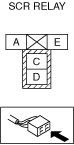
PURPOSE: INSPECT SCR RELAY
• Switch the ignition off.
• Remove the SCR relay.
(See RELAY LOCATION [(E)].)
• Inspect the SCR relay.
(See RELAY INSPECTION.)
• Is there any malfunction?
|
Yes
|
Repair or replace the malfunctioning location and perform the repair completion verification.
|
|
No
|
Go to the next step.
|
||
|
5
|
PURPOSE: INSPECT MEIN 200 A FUSE
• Remove the MEIN 200 A Fuse.
• Inspect the MEIN 200 A Fuse.
• Is the fuse normal?
|
Yes
|
Reinstall the MEIN 200 A Fuse, then go to the next step.
|
|
No
|
Replace the MEIN 200 A Fuse and perform the repair completion verification.
|
||
|
6
|
PURPOSE: INSPECT F13 15 A FUSE
• Remove the F13 15 A Fuse.
• Inspect the F13 15 A Fuse.
• Is the fuse normal?
|
Yes
|
Reinstall the F13 15 A Fuse, then go to the next step.
|
|
No
|
Replace the F13 15 A Fuse and perform the repair completion verification.
|
||
|
7
|
PURPOSE: INSPECT SCR RELAY POWER SUPPLY CIRCUIT FOR SHORT TO GROUND OR OPEN CIRCUIT
• Inspect the applicable circuit for a short to ground or open circuit.
(See CIRCUIT INSPECTION.)
• Is the circuit normal?
|
Yes
|
Go to the next step.
|
|
No
|
Repair or replace the malfunctioning location and perform the repair completion verification.
|
||
|
8
|
PURPOSE: INSPECT NOx SENSOR POWER SUPPLY CIRCUIT FOR SHORT TO GROUND OR OPEN CIRCUIT
• Inspect the applicable circuit for a short to ground or open circuit.
(See CIRCUIT INSPECTION.)
• Is the circuit normal?
|
Yes
|
Go to the next step.
|
|
No
|
Repair or replace the malfunctioning location and perform the repair completion verification.
|
||
|
9
|
INSPECT NOx SENSOR GROUND CIRCUIT AND CAN COMMUNICATION LINE FOR OPEN CIRCUIT
• Inspect the applicable circuit for open circuit.
(See CIRCUIT INSPECTION.)
• Is the circuit normal?
|
Yes
|
Replace the NOx sensor, then go to the next step.
|
|
No
|
Repair or replace the malfunctioning location and perform the repair completion verification.
|
||
|
Repair completion verification 1
|
PURPOSE: VERIFY THAT VEHICLE IS REPAIRED
• Install/connect the part removed/disconnected during the troubleshooting procedure.
• Clear the DTC recorded in the memory.
(See CLEARING DTC.)
• Replicate the vehicle conditions at the time the DTC was detected using the following procedure.
• Perform the DTC inspection for the PCM.
(See DTC INSPECTION.)
• Is the same Pending DTC present?
|
Yes
|
Refer to the controller area network (CAN) malfunction diagnosis flow to inspect for a CAN communication error.
If the CAN communication is normal, perform the diagnosis from Step 1.
• If the malfunction recurs, replace the PCM, then go to the next step.
|
|
No
|
Go to the next step.
|
||
|
Repair completion verification 2
|
PURPOSE: VERIFY IF OTHER DTCs DISPLAYED
• Perform the DTC inspection.
(See DTC INSPECTION.)
• Are any other DTCs displayed?
|
Yes
|
Repair the malfunctioning location according to the applicable DTC troubleshooting.
|
|
No
|
DTC troubleshooting completed.
|