DTC P20F8:00 [PCM (SKYACTIV-X)]
id0102u9203400
Details On DTCs
Description |
Swirl control circuit range/performance problem |
||
---|---|---|---|
Detection condition
|
Determination conditions
|
• The actual opening angle of the swirl control valve is larger or smaller than its target opening angle for the specified time.
|
|
Preconditions
|
• Battery voltage: above 11 V*1
• Engine coolant temperature: 20 °C {68 °F} or more*1
• The following DTCs are not detected:
*1: Standard can be verified by displaying PIDs using M-MDS
|
||
Drive cycle
|
• 1
|
||
Self test type
|
• CMDTC self test, KOEO self test, KOER self test
|
||
Sensor used
|
• Swirl control valve position sensor
|
||
Fail-safe function
|
• Limits intake air amount
• Stops the EGR control.
|
||
Vehicle status when DTCs are output
|
• Not applicable
|
||
Possible cause
|
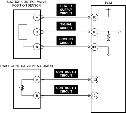
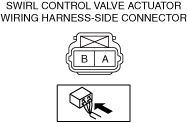
• Swirl control valve actuator connector or terminals malfunction
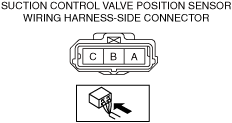
• Swirl control valve position sensor connector or terminals malfunction
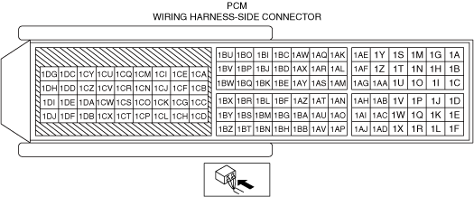
• PCM connector or terminals malfunction
• Short to ground in swirl control valve actuator control circuit
• Short to power supply in swirl control valve actuator control circuit
• Open circuit in swirl control valve actuator control circuit
• Short to ground in any of the following swirl control valve position sensor circuits.
• Short to power supply in any of the following swirl control valve position sensor circuits.
• Open circuit in any of the following swirl control valve position sensor circuits.
• Swirl control valve actuator malfunction
• Swirl control valve position sensor malfunction
• PCM malfunction
|
||
![]() |
|||
![]() |
![]() |
||
![]() |
Function Explanation (DTC Detection Outline)
Repeatability Verification Procedure
1. Switch the ignition ON (engine off).
2. Display PID IMRC_ACT and simulation item IMRC_COMD using the M-MDS.(See PID/DATA MONITOR INSPECTION.)(See SIMULATION INSPECTION.)
3. Drive the IMRC_COMD from 0 ° to the maximum value using the simulation item IMRC_COMD.
PID Item/Simulation Item Used In Diagnosis
PID/DATA monitor item table
PIDs |
Reference |
---|---|
IMRC_ACT
|
Simulation item table
Simulation items |
Reference |
---|---|
IMRC_COMD
|
Function Inspection Using M-MDS
Step |
Inspection |
Results |
Action |
---|---|---|---|
1
|
PURPOSE: VERIFY RELATED REPAIR INFORMATION OR SERVICE INFORMATION AVAILABILITY
• Verify related Service Bulletins, on-line repair information, or Service Information availability.
• Is any related Information available?
|
Yes
|
Perform repair or diagnosis according to the available information.
• If the vehicle is not repaired, go to the next step.
|
No
|
Go to the next step.
|
||
2
|
PURPOSE: RECORD VEHICLE STATUS WHEN DTC WAS DETECTED TO UTILIZE WITH REPEATABILITY VERIFICATION
• Record the freeze frame data/snapshot data.
|
—
|
Go to the next step.
|
4
|
PURPOSE: VERIFY CONNECTOR CONNECTIONS
• Access the following PIDs using the M-MDS:
(See PID/DATA MONITOR INSPECTION.)
• Does the PID value fluctuate when the following connectors are shaken?
|
Yes
|
Repair or replace the applicable wiring harness or connector parts.
Go to Troubleshooting Diagnostic Procedure to perform the repair completion verification.
|
No
|
Go to Troubleshooting Diagnostic Procedure to perform the procedure from Step 1.
|
Troubleshooting Diagnostic Procedure
Step |
Inspection |
Results |
Action |
---|---|---|---|
1
|
INSPECT SWIRL CONTROL VALVE ACTUATOR CONNECTOR FOR MALFUNCTION
• Inspect the applicable connector and terminal.
(See CONNECTOR INSPECTION.)
• Are the connector and terminal normal?
|
Yes
|
Go to the next step.
|
No
|
Repair or replace the malfunctioning location and perform the repair completion verification.
|
||
2
|
INSPECT SWIRL CONTROL VALVE ACTUATOR CONTROL CIRCUIT FOR SHORT TO GROUND
• Inspect the applicable circuit for a short to ground.
(See CIRCUIT INSPECTION.)
• Is the circuit normal?
|
Yes
|
Go to the next step.
|
No
|
Repair or replace the malfunctioning location and perform the repair completion verification.
|
||
3
|
INSPECT SWIRL CONTROL VALVE ACTUATOR CONTROL CIRCUIT FOR SHORT TO POWER SUPPLY
• Inspect the applicable circuit for a short to power supply.
(See CIRCUIT INSPECTION.)
• Is the circuit normal?
|
Yes
|
Go to the next step.
|
No
|
Repair or replace the malfunctioning location and perform the repair completion verification.
|
||
4
|
INSPECT SWIRL CONTROL VALVE ACTUATOR CONTROL CIRCUIT FOR OPEN CIRCUIT
• Inspect the applicable circuit for open circuit.
(See CIRCUIT INSPECTION.)
• Is the circuit normal?
|
Yes
|
Go to the next step.
|
No
|
Repair or replace the malfunctioning location and perform the repair completion verification.
|
||
5
|
INSPECT SWIRL CONTROL VALVE POSITION SENSOR POWER SUPPLY CIRCUIT AND SIGNAL CIRCUIT FOR SHORT TO GROUND
• Inspect the applicable circuit for a short to ground.
(See CIRCUIT INSPECTION.)
• Is the circuit normal?
|
Yes
|
Go to the next step.
|
No
|
Repair or replace the malfunctioning location and perform the repair completion verification.
|
||
6
|
INSPECT SWIRL CONTROL VALVE POSITION SENSOR SIGNAL CIRCUIT AND GROUND CIRCUIT FOR SHORT TO POWER SUPPLY
• Inspect the applicable circuit for a short to power supply.
(See CIRCUIT INSPECTION.)
• Is the circuit normal?
|
Yes
|
Go to the next step.
|
No
|
Repair or replace the malfunctioning location and perform the repair completion verification.
|
||
7
|
INSPECT SWIRL CONTROL VALVE POSITION SENSOR POWER SUPPLY CIRCUIT, SIGNAL CIRCUIT AND GROUND CIRCUIT FOR OPEN CIRCUIT
• Inspect the applicable circuit for open circuit.
(See CIRCUIT INSPECTION.)
• Is the circuit normal?
|
Yes
|
Go to the next step.
|
No
|
Repair or replace the malfunctioning location and perform the repair completion verification.
|
||
8
|
INSPECT SWIRL CONTROL VALVE POSITION SENSOR FOR MALFUNCTION
• Inspect the applicable part.
• Is the circuit normal?
|
Yes
|
Repair or replace the intake manifold and perform the repair completion verification.
|
No
|
Repair or replace the malfunctioning location and perform the repair completion verification.
|
||
Repair completion verification 1
|
PURPOSE: VERIFY THAT VEHICLE IS REPAIRED
• Install/connect the part removed/disconnected during the troubleshooting procedure.
• Clear the DTC recorded in the memory.
(See CLEARING DTC.)
• Replicate the vehicle conditions at the time the DTC was detected using the following procedure.
• Perform the DTC inspection for the PCM.
(See DTC INSPECTION.)
• Is the same Pending DTC present?
|
Yes
|
Refer to the controller area network (CAN) malfunction diagnosis flow to inspect for a CAN communication error.
If the CAN communication is normal, perform the diagnosis from Step 1.
• If the malfunction recurs, replace the PCM, then go to the next step.
|
No
|
Go to the next step.
|
||
Repair completion verification 2
|
PURPOSE: VERIFY IF OTHER DTCs DISPLAYED
• Perform the DTC inspection.
(See DTC INSPECTION.)
• Are any other DTCs displayed?
|
Yes
|
Repair the malfunctioning location according to the applicable DTC troubleshooting.
|
No
|
DTC troubleshooting completed.
|