DTC P1BC9:00 [PCM (SKYACTIV-X)]
id0102u9746500
Details On DTCs
Description |
Integrated starter generator (ISG): IG power supply malfunction |
||
---|---|---|---|
Detection condition
|
Determination conditions
|
• The PCM detects that the integrated starter generator (ISG) stores the DTC P1BC9:00.
|
|
Preconditions
|
• Not applicable
|
||
Malfunction determination period
|
• 5 s period
|
||
Drive cycle
|
• 1
|
||
Self test type
|
• CMDTC self test, KOEO self test
|
||
Sensor used
|
• Integrated starter generator (ISG)
|
||
Fail-safe function
|
• Inhibits the conventional power generation mode (non-regenerative) control.
• Inhibits the regenerative braking control.
• Inhibits the motor assist control.
• Inhibits the non-power generation control.
• Inhibits engine-stop by operating the i-stop function.
|
||
Vehicle status when DTCs are output
|
• Not applicable
|
||
Possible cause
|
• DTCs are stored in the integrated starter generator (ISG).
• IG1 relay No.1 malfunction
• PCM connector or terminals malfunction
• Short to ground or open circuit in PCM power supply circuit
• Short to power supply in wiring harness between IG1 relay No.1 and PCM
• Exhaust electrical variable valve timing relay malfunction
• Integrated starter generator (ISG) connector or terminals malfunction
• Short to ground or open circuit in integrated starter generator (ISG) power supply circuit
• Short to power supply in wiring harness between exhaust electrical variable valve timing relay and integrated starter generator (ISG)
• Integrated starter generator (ISG) malfunction (internal malfunction)
• CAN communication line malfunction between PCM and integrated starter generator (ISG)
• PCM malfunction
|
||
![]() |
|||
![]() |
![]() |
||
![]() |
![]() |
Function Explanation (DTC Detection Outline)
Repeatability Verification Procedure
1. Start the engine.
2. Access the following snapshot data using the M-MDS:
(See SNAPSHOT DATA TABLE [PCM (SKYACTIV-X)].)
3. Try to reproduce the malfunction by driving the vehicle based on the values in the snapshot data.
PID Item/Simulation Item Used In Diagnosis
Function Inspection Using M-MDS
Step |
Inspection |
Results |
Action |
---|---|---|---|
1
|
PURPOSE: VERIFY RELATED REPAIR INFORMATION OR SERVICE INFORMATION AVAILABILITY
• Verify related Service Bulletins, on-line repair information, or Service Information availability.
• Is any related Information available?
|
Yes
|
Perform repair or diagnosis according to the available information.
• If the vehicle is not repaired, go to the next step.
|
No
|
Go to the next step.
|
||
2
|
PURPOSE: RECORD VEHICLE STATUS WHEN DTC WAS DETECTED TO UTILIZE WITH REPEATABILITY VERIFICATION
• Record the freeze frame data/snapshot data.
|
—
|
Go to the next step.
|
3
|
PURPOSE: INSPECT FOR OTHER RELATED DTCs
• Perform the DTC inspection for the following modules.
(See DTC INSPECTION.)
• Are any of the following DTCs displayed?
Integrated starter generator (ISG)
DC-DC converter (Mazda M Hybrid)
|
Yes
|
Go to Troubleshooting Diagnostic Procedure to perform the procedure from Step 1.
|
No
|
Go to the next step.
|
||
4
|
PURPOSE: VERIFY COMMUNICATION CONDITION WITH INTEGRATED STARTER GENERATOR (ISG)
• Perform the vehicle ID using the M-MDS.
• Verify the quick check display (network view).
• Is the integrated starter generator (ISG) displayed in red or blue?
|
Yes
|
Go to Troubleshooting Diagnostic Procedure to perform the procedure from Step 5.
|
No
|
Go to the next step.
|
||
5
|
PURPOSE: VERIFY INTEGRATED STARTER GENERATOR (ISG) DTCs
• Perform the DTC inspection for the integrated starter generator (ISG).
(See DTC INSPECTION.)
• Is the DTC P1BC9:00 displayed?
|
Yes
|
Repair the malfunctioning location according to the applicable DTC troubleshooting.
|
No
|
Go to the next step.
|
||
6
|
PURPOSE: VERIFY INTEGRATED STARTER GENERATOR (ISG) DTCs AFTER CLEARING DTCs
• Clear the DTC recorded in the memory.
(See CLEARING DTC.)
• Perform the DTC inspection for the integrated starter generator (ISG).
(See DTC INSPECTION.)
• Are any DTCs displayed?
|
Yes
|
Repair the malfunctioning location according to the applicable DTC troubleshooting.
|
No
|
Intermittent concern exists.
• Go to Troubleshooting Diagnostic Procedure to perform the repair completion verification.
|
Troubleshooting Diagnostic Procedure
Step |
Inspection |
Results |
Action |
---|---|---|---|
1
|
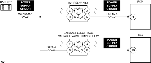
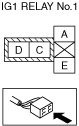
PURPOSE: INSPECT IG1 RELAY No.1 FOR MALFUNCTION
• Inspect the applicable part
(See RELAY INSPECTION.)
• Is the part normal?
|
Yes
|
Install the relay, then go to the next step.
(See RELAY LOCATION [(E)].)
|
No
|
Repair or replace the malfunctioning location then perform the repair completion verification.
(See RELAY LOCATION [(E)].)
|
||
2
|
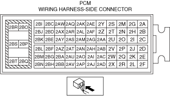
PURPOSE: INSPECT PCM CONNECTOR FOR MALFUNCTION
• Inspect the applicable connector and terminal.
(See CONNECTOR INSPECTION.)
• Are the connector and terminal normal?
|
Yes
|
Go to the next step.
|
No
|
Repair or replace the malfunctioning location then perform the repair completion verification.
|
||
3
|
PURPOSE: INSPECT PCM POWER SUPPLY CIRCUIT FOR SHORT TO GROUND AND OPEN CIRCUIT
• Inspect the power supply circuit for an open circuit and short to ground.
(See CIRCUIT INSPECTION.)
• Is the circuit normal?
|
Yes
|
Go to the next step.
|
No
|
Repair or replace the malfunctioning location then perform the repair completion verification.
|
||
4
|
PURPOSE: INSPECT WIRING HARNESS BETWEEN IG1 RELAY No.1 AND PCM FOR SHORT TO POWER SUPPLY
• Inspect the applicable circuit for a short to power supply.
(See CIRCUIT INSPECTION.)
• Is the circuit normal?
|
Yes
|
Go back to Step 3 of the “Function Inspection Using M-MDS” to perform the procedure again.
|
No
|
Repair or replace the malfunctioning location then perform the repair completion verification.
|
||
5
|
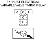
PURPOSE: INSPECT EXHAUST ELECTRICAL VARIABLE VALVE TIMING RELAY FOR MALFUNCTION
• Inspect the applicable part
(See RELAY INSPECTION.)
• Is the part normal?
|
Yes
|
Install the relay, then go to the next step.
(See RELAY LOCATION [(E)].)
|
No
|
Repair or replace the malfunctioning location then perform the repair completion verification.
(See RELAY LOCATION [(E)].)
|
||
6
|
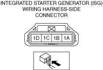
PURPOSE: INSPECT INTEGRATED STARTER GENERATOR (ISG) CONNECTOR FOR MALFUNCTION
• Inspect the applicable connector and terminal.
(See CONNECTOR INSPECTION.)
• Are the connector and terminal normal?
|
Yes
|
Go to the next step.
|
No
|
Repair or replace the malfunctioning location then perform the repair completion verification.
|
||
7
|
PURPOSE: INSPECT INTEGRATED STARTER GENERATOR (ISG) POWER SUPPLY CIRCUIT FOR SHORT TO GROUND AND OPEN CIRCUIT
• Inspect the power supply circuit for an open circuit and short to ground.
(See CIRCUIT INSPECTION.)
• Is the circuit normal?
|
Yes
|
Go to the next step.
|
No
|
Repair or replace the malfunctioning location then perform the repair completion verification.
|
||
8
|
PURPOSE: INSPECT WIRING HARNESS BETWEEN EXHAUST ELECTRICAL VARIABLE VALVE TIMING RELAY AND INTEGRATED STARTER GENERATOR (ISG) FOR SHORT TO POWER SUPPLY
• Inspect the applicable circuit for a short to power supply.
(See CIRCUIT INSPECTION.)
• Is the circuit normal?
|
Yes
|
Go to the next step.
|
No
|
Repair or replace the malfunctioning location then perform the repair completion verification.
|
||
9
|
PURPOSE: INSPECT INTEGRATED STARTER GENERATOR (ISG) INTERNAL CIRCUIT FOR SHORT TO GROUND
• Inspect for continuity between the integrated starter generator (ISG) terminal 1B (parts-side) and body ground.
• Is there continuity?
|
Yes
|
Replace the integrated starter generator (ISG) then perform the repair completion verification.
|
No
|
Short to power supply in the integrated starter generator (ISG) can be considered the cause of the malfunction.
• Refer to the controller area network (CAN) malfunction diagnosis flow to inspect for a CAN communication error.
|
||
Repair completion verification 1
|
PURPOSE: VERIFY THAT VEHICLE IS REPAIRED
• Install/connect the part removed/disconnected during the troubleshooting procedure.
• Clear the DTC recorded in the memory.
(See CLEARING DTC.)
• Replicate the vehicle conditions at the time the DTC was detected using the following procedure.
• Perform the DTC inspection for the PCM.
(See DTC INSPECTION.)
• Is the same Pending DTC present?
|
Yes
|
Refer to the controller area network (CAN) malfunction diagnosis flow to inspect for a CAN communication error.
If the CAN communication is normal, perform the diagnosis from Step 1.
• If the malfunction recurs, replace the PCM, then go to the next step.
|
No
|
Go to the next step.
|
||
Repair completion verification 2
|
PURPOSE: VERIFY IF OTHER DTCs DISPLAYED
• Perform the DTC inspection.
(See DTC INSPECTION.)
• Are any other DTCs displayed?
|
Yes
|
Repair the malfunctioning location according to the applicable DTC troubleshooting.
|
No
|
DTC troubleshooting completed.
|