|
1
|
RECORD VEHICLE STATUS WHEN DTC WAS DETECTED TO UTILIZE WITH REPEATABILITY VERIFICATION
• Record the snapshot data.
-
Note
-
• Recording can be facilitated using the screen capture function of the PC.
|
—
|
Go to the next step.
|
|
2
|
VERIFY DC-DC CONVERTER (Mazda M Hybrid) DTC
• Perform the DTC inspection for the DC-DC converter (Mazda M Hybrid).
• Is the following DTC displayed and is the displayed DTC a present malfunction?
-
― P1628:62
|
Yes
|
Go to Step 4.
|
|
No
|
Go to the next step.
|
|
3
|
VERIFY Mazda M Hybrid BATTERY DTC
• Perform the DTC inspection for the Mazda M Hybrid battery.
• Is the following DTC displayed and is the displayed DTC a present malfunction?
-
― P1793:12
-
― P1793:14
|
Yes
|
Go to the next step.
|
|
No
|
Go to Step 6.
|
|
4
|
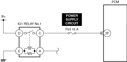
INSPECT PCM POWER SUPPLY CIRCUIT FOR SHORT TO GROUND
• Inspect the applicable circuit for a short to ground.
• Is the circuit normal?
|
Yes
|
Go to the next step.
|
|
No
|
Repair or replace the malfunctioning location and perform the repair completion verification 1.
|
|
5
|
INSPECT PCM POWER SUPPLY CIRCUIT FOR OPEN CIRCUIT
• Inspect the applicable circuit for open circuit.
• Is the circuit normal?
|
Yes
|
Go to the next step.
|
|
No
|
Repair or replace the malfunctioning location and perform the repair completion verification 1.
|
|
6
|
VERIFY PCM DTCs
• Perform the DTC inspection for the PCM.
• Are any DTCs displayed?
|
Yes
|
Repair the malfunctioning location according to the applicable DTC troubleshooting.
|
|
No
|
Go to the next step.
|
|
7
|
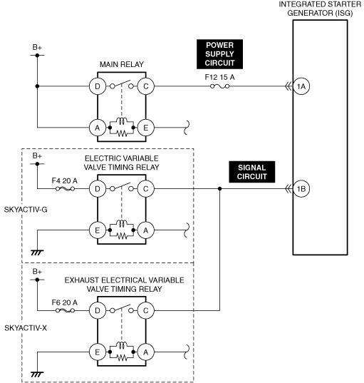
INSPECT F4 20 A FUSE (SKYACTIV-G)/F6 20 A FUSE (SKYACTIV-X)
• Switch the ignition off.
• Remove the F4 20 A fuse (SKYACTIV-G)/F6 20 A fuse (SKYACTIV-X).
• Inspect the F4 20 A fuse (SKYACTIV-G)/F6 20 A fuse (SKYACTIV-X).
• Is the fuse normal?
|
Yes
|
Reinstall the F4 20 A fuse (SKYACTIV-G)/F6 20 A fuse (SKYACTIV-X), then go to the next step.
|
|
No
|
Replace the F4 20 A fuse (SKYACTIV-G)/F6 20 A fuse (SKYACTIV-X) and perform the repair completion verification 1.
|
|
8
|
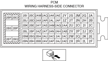
INSPECT PCM CONNECTOR FOR MALFUNCTION
• Inspect the applicable connector and terminal.
• Are the connector and terminal normal?
|
Yes
|
Go to the next step.
|
|
No
|
Repair or replace the malfunctioning location and perform the repair completion verification 1.
|
|
9
|
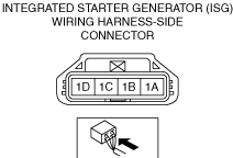
INSPECT INTEGRATED STARTER-GENERATOR (ISG) CONNECTOR FOR MALFUNCTION
• Inspect the applicable connector and terminal.
• Are the connector and terminal normal?
|
Yes
|
Go to the next step.
|
|
No
|
Repair or replace the malfunctioning location and perform the repair completion verification 1.
|
|
10
|
INSPECT INTEGRATED STARTER-GENERATOR (ISG) INTERNAL CIRCUIT FOR SHORT TO GROUND
• Verify that the integrated starter generator (ISG) and PCM connectors are disconnected.
• Inspect for continuity between integrated starter generator (ISG) terminal 1B (part-side) and body ground.
• Is there continuity?
|
Yes
|
Replace the integrated starter generator (ISG) and perform the repair completion verification 2.
|
|
No
|
Go to the next step.
|
|
11
|
INSPECT INTEGRATED STARTER-GENERATOR (ISG) SIGNAL CIRCUIT FOR OPEN AND SHORT TO GROUND
• Access the following PIDs using the M-MDS:
Integrated starter generator (ISG):
-
― IG_SIG
• Does the PID value fluctuate when the following connectors are shaken?
-
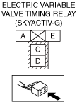
― Electric variable valve timing relay (SKYACTIV-G)
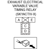
― Exhaust electrical variable valve timing relay (SKYACTIV-X)
― Integrated starter generator (ISG)
|
Yes
|
Repair or replace the applicable wiring harness or connector parts.
Go to repair completion verification 1.
|
|
No
|
Go to the next step.
|
|
12
|
INSPECT PCM FOR MALFUNCTION DEPENDING ON REPEATABILITY
• Install/connect the part removed/disconnected during the troubleshooting procedure.
• Clear the DTC recorded in the memory.
• Start the engine.
• Access the following PIDs using the M-MDS:
Integrated starter generator (ISG):
-
― B-ISG_RPM
PCM:
-
― ENG_RPM
― VSS
― ECT
-
Warning
-
• When the M-MDS is used to observe monitor system status while driving, be sure to have another technician with you, or record the data in the M-MDS using the PID/DATA MONITOR AND RECORD capturing function and inspect later.
• While performing this step, always operate the vehicle in a safe and lawful manner.
-
Note
-
• Match the engine coolant temperature in the recorded snapshot data, the vehicle speed, and engine speed values to the best extent possible while driving the vehicle.
• Try to reproduce the malfunction by driving the vehicle based on the values in the snapshot data.
• Perform the DTC inspection for the integrated starter generator (ISG).
• Is the same Pending DTC present?
|
Yes
|
Refer to the controller area network (CAN) malfunction diagnosis flow to inspect for a CAN communication error.
If the CAN communication is normal, perform the diagnosis from Step 1.
• If the malfunction recurs, replace the PCM.
Go to repair completion verification 1.
|
|
No
|
The system is normal. (Explain to the customer that a malfunction was detected temporarily, but the vehicle is currently normal.)
Go to repair completion verification 2.
|
|
Repair completion verification 1
|
VERIFY THAT VEHICLE IS REPAIRED
• Install/connect the part removed/disconnected during the troubleshooting procedure.
• Clear the DTC recorded in the memory.
• Replicate the vehicle conditions at the time the DTC was detected using the following procedure.
-
― Start the engine.
― Access the following PIDs using the M-MDS:
Integrated starter generator (ISG):
-
• B-ISG_RPM
PCM:
-
• ENG_RPM
• VSS
• ECT
-
Warning
-
• When the M-MDS is used to observe monitor system status while driving, be sure to have another technician with you, or record the data in the M-MDS using the PID/DATA MONITOR AND RECORD capturing function and inspect later.
• While performing this step, always operate the vehicle in a safe and lawful manner.
-
Note
-
• Match the engine coolant temperature in the recorded snapshot data, the vehicle speed, and engine speed values to the best extent possible while driving the vehicle.
― Try to reproduce the malfunction by driving the vehicle based on the values in the snapshot data.
• Perform the DTC inspection for the integrated starter generator (ISG).
• Is the same Pending DTC present?
|
Yes
|
Refer to the controller area network (CAN) malfunction diagnosis flow to inspect for a CAN communication error.
If the CAN communication is normal, perform the diagnosis from Step 1.
• If the malfunction recurs, replace the integrated starter generator (ISG), then go to the next step.
|
|
No
|
Go to the next step.
|
|
Repair completion verification 2
|
VERIFY IF OTHER DTCs DISPLAYED
• Perform the DTC inspection.
• Are any other DTCs displayed?
|
Yes
|
Repair the malfunctioning location according to the applicable DTC troubleshooting.
|
|
No
|
DTC troubleshooting completed.
|