 |
ac3wzw00004700
LOWER CASE REMOVAL/INSTALLATION [SKYACTIV-D 1.8]
id0114q9266300
Replacement Part
|
Fuel main hose No.1
Quantity: 1
Location of use: Lower case
|
Fuel return hose No.1
Quantity: 1
Location of use: Lower case
|
Fuel return hose No.2
Quantity: 1
Location of use: Lower case
|
|
Fuel main hose No.2
Quantity: 1
Location of use: Lower case
|
Fuel return hose No.3
Quantity: 1
Location of use: Lower case
|
—
|
1. Disconnect the negative battery terminal. (See NEGATIVE BATTERY TERMINAL DISCONNECTION/CONNECTION [(E)].)
2. Remove the engine cover. (See ENGINE COVER REMOVAL/INSTALLATION [SKYACTIV-D 1.8].)
3. Complete the “BEFORE SERVICE PRECAUTION”. (See BEFORE SERVICE PRECAUTION [SKYACTIV-D 1.8].)
4. Remove the battery and the battery tray. (See BATTERY REMOVAL/INSTALLATION [SKYACTIV-D 1.8].)
5. Remove the following parts as a single unit: (See INTAKE-AIR SYSTEM REMOVAL/INSTALLATION [SKYACTIV-D 1.8].)
6. Disconnect the CMP sensor connector. (See CAMSHAFT POSITION (CMP) SENSOR REMOVAL/INSTALLATION [SKYACTIV-D 1.8].)
7. Disconnect the fuel injector connector. (See FUEL INJECTOR REMOVAL/INSTALLATION [SKYACTIV-D 1.8].)
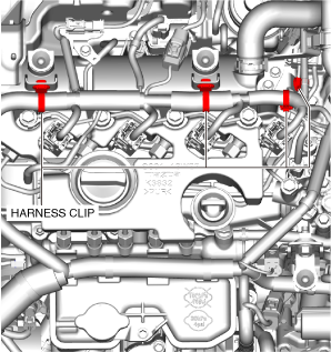
8. Disconnect the wiring harness clips shown in the figure.
ac3wzw00004700
|
9. Disconnect the exhaust gas temperature sensor No.1 connector. (See EXHAUST GAS TEMPERATURE SENSOR REMOVAL/INSTALLATION [SKYACTIV-D 1.8].)
10. Disconnect the exhaust gas temperature sensor No.1 connector clip. (See EXHAUST GAS TEMPERATURE SENSOR REMOVAL/INSTALLATION [SKYACTIV-D 1.8].)
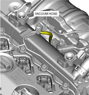
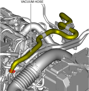
11. Disconnect the vacuum hose shown in the figure. (See TURBOCHARGER SOLENOID VALVE REMOVAL/INSTALLATION [SKYACTIV-D 1.8].)
ac3wzw00004701
|
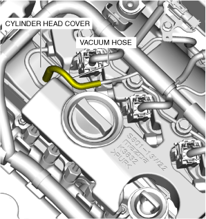
12. Disconnect the vacuum hose connected to the cylinder head cover.
ac3wzw00004702
|
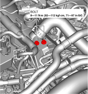
13. Remove the bolts shown in the figure.
ac3wzw00004703
|
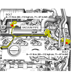
14. Remove the vacuum pipe installation bolt and set the vacuum pipe aside so that it does not interfere with the servicing.
ac3wzw00004704
|
15. Remove the fuel return pipe. (See FUEL INJECTOR REMOVAL/INSTALLATION [SKYACTIV-D 1.8].)
16. Remove the fuel injector insulator. (See FUEL INJECTOR REMOVAL/INSTALLATION [SKYACTIV-D 1.8].)
17. Remove the vacuum hose shown in the figure. (See VACUUM LINE INSPECTION [SKYACTIV-D 1.8].)
ac3wzw00004705
|
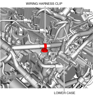
18. Disconnect the wiring harness clip shown in the figure.
ac3wzw00004706
|
19. Remove the fuel feed pipe. (See SUPPLY PUMP REMOVAL/INSTALLATION [SKYACTIV-D 1.8].)
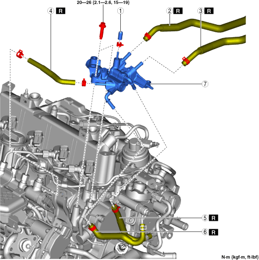
20. Remove in the order shown in the figure.
21. Install in the reverse order of removal.
22. Complete the “AFTER SERVICE PRECAUTION”. (See AFTER SERVICE PRECAUTION [SKYACTIV-D 1.8].)
am3zzw00031295
|
|
1
|
Blind cap
(See Blind Cap Installation Note.)
|
|
2
|
Fuel main hose No.1
|
|
3
|
Fuel return hose No.1
|
|
4
|
Fuel return hose No.2
|
|
5
|
Fuel main hose No.2
|
|
6
|
Fuel return hose No.3
|
|
7
|
Lower case
|
Fuel Return Hose No.3 Installation Note
1. Install fuel return hose No.3 as shown in the figure.
am3zzw00032991
|
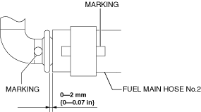
Fuel Main Hose No.2 Installation Note
1. Install fuel main hose No.2 as shown in the figure.
am3zzw00032992
|
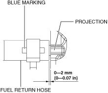
Fuel Return Hose No.2 Installation Note
1. Install fuel return hose No.2 as shown in the figure.
Lower case side
am3zzw00032993
|
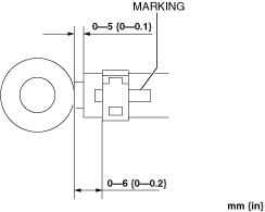
Common rail side
am3zzw00032994
|
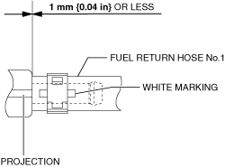
Fuel Return Hose No.1 Installation Note
1. Install fuel return hose No.1 as shown in the figure.
am3zzw00032995
|
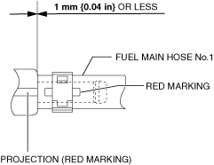
Fuel Main Hose No.1 Installation Note
1. Install fuel main hose No.1 as shown in the figure.
am3zzw00032996
|
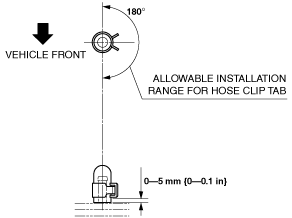
Blind Cap Installation Note
1. Install blind cap as shown in the figure.
am2zzw00012081
|