 |
ac3wzw00004732
SUPPLY PUMP REMOVAL/INSTALLATION [SKYACTIV-D 1.8]
id0114q9805700
Replacement Part
|
Injection pipe (supply pump side)
Quantity: 1
Location of use: Supply pump
|
Clip
Quantity: 1
Location of use: Fuel feed pipe
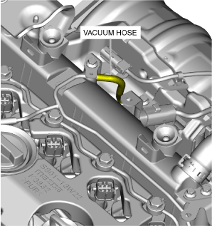
|
Washer
Quantity: 2
Location of use: Fuel feed pipe
|
|
Washer
Quantity: 2
Location of use: Fuel main hose Connector
|
Washer
Quantity: 2
Location of use: Fuel return hose Connector
|
O-ring
Quantity: 1
Location of use: Supply pump
|
|
Fuel main hose
Quantity: 1
Location of use: Supply pump
|
Fuel return hose
Quantity: 1
Location of use: Supply pump
|
—
|
Oil and Chemical Type
|
Engine oil
Type: Recommended oil
|
Operation After Replacing or Removal/Installation Supply Pump
1. If the supply pump is replaced or removed/installed, perform the following procedure.
|
STEP |
ACTION |
PAGE/CONDITION |
|---|---|---|
|
1
|
Perform supply pump data reset procedure.
|
|
|
2
|
Switch the ignition off.
|
—
|
|
3
|
Wait for 30 s or more.
|
—
|
|
4
|
Switch the ignition ON (engine off).
|
—
|
|
5
|
Perform KOEO self-test procedure.
|
(See DTC INSPECTION.)
|
|
6
|
Maintain the idle status for 30 s with the following condition met.
• ECT: 60—100 °C {140—212 °F}
|
—
|
|
7
|
Perform KOER self-test procedure.
|
(See DTC INSPECTION.)
|
Supply Pump Removal/Installation
1. Disconnect the negative battery terminal. (See NEGATIVE BATTERY TERMINAL DISCONNECTION/CONNECTION [(E)].)
2. Remove the engine cover. (See ENGINE COVER REMOVAL/INSTALLATION [SKYACTIV-D 1.8].)
3. Complete the “BEFORE SERVICE PRECAUTION”. (See BEFORE SERVICE PRECAUTION [SKYACTIV-D 1.8].)
4. Remove the following parts as a single unit: (See INTAKE-AIR SYSTEM REMOVAL/INSTALLATION [SKYACTIV-D 1.8].)
5. Remove the battery and the battery tray. (See BATTERY REMOVAL/INSTALLATION [SKYACTIV-D 1.8].)
6. Disconnect the ECT sensor connector. (See ENGINE COOLANT TEMPERATURE (ECT) SENSOR REMOVAL/INSTALLATION [SKYACTIV-D 1.8].)
7. Disconnect the suction control valve connector.
8. Disconnect the CMP sensor connector. (See CAMSHAFT POSITION (CMP) SENSOR REMOVAL/INSTALLATION [SKYACTIV-D 1.8].)
9. Disconnect the fuel injector connector. (See FUEL INJECTOR REMOVAL/INSTALLATION [SKYACTIV-D 1.8].)
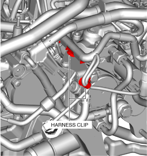
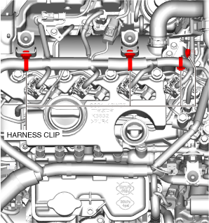
10. Disconnect the wiring harness clips shown in the figure.
ac3wzw00004732
|
11. Disconnect the exhaust gas temperature sensor No.1 connector. (See EXHAUST GAS TEMPERATURE SENSOR REMOVAL/INSTALLATION [SKYACTIV-D 1.8].)
12. Disconnect the exhaust gas temperature sensor No.1 connector clip. (See EXHAUST GAS TEMPERATURE SENSOR REMOVAL/INSTALLATION [SKYACTIV-D 1.8].)
13. Disconnect the vacuum hose shown in the figure. (See TURBOCHARGER SOLENOID VALVE REMOVAL/INSTALLATION [SKYACTIV-D 1.8].)
ac3wzw00004733
|
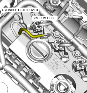
14. Disconnect the vacuum hose connected to the cylinder head cover.
ac3wzw00004734
|
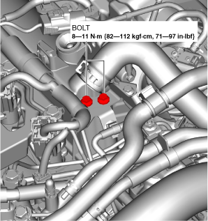
15. Remove the bolts shown in the figure.
ac3wzw00004735
|
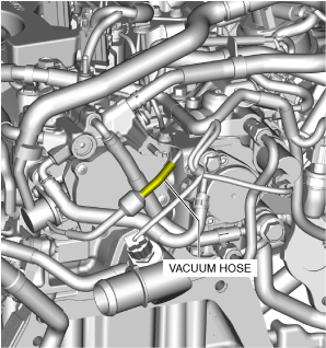
16. Disconnect the vacuum hose shown in the figure.
ac3wzw00004736
|
17. Disconnect the wiring harness clip shown in the figure.
ac3wzw00004737
|
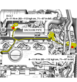
18. Remove the vacuum pipe.
ac3wzw00004738
|
19. Remove the fuel return pipe. (See FUEL INJECTOR REMOVAL/INSTALLATION [SKYACTIV-D 1.8].)
20. Remove the fuel injector insulator. (See FUEL INJECTOR REMOVAL/INSTALLATION [SKYACTIV-D 1.8].)
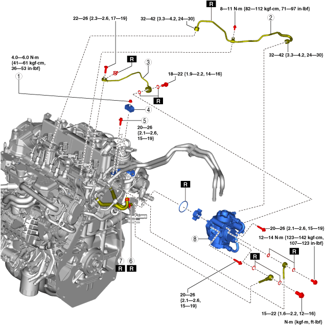
21. Remove in the order shown in the figure.
22. Install in the reverse order of removal.
23. Complete the “AFTER SERVICE PRECAUTION”. (See AFTER SERVICE PRECAUTION [SKYACTIV-D 1.8].)
am3zzw00031296
|
|
1
|
Clip installation nut
|
|
2
|
Injection pipe (supply pump side)
|
|
3
|
Fuel feed pipe
|
|
4
|
Clip
|
|
5
|
Bracket installation bolts
|
|
6
|
Fuel main hose
|
|
7
|
Fuel return hose
|
|
8
|
Supply pump
|
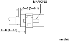
Fuel return hose installation note
1. Install fuel return hose as shown in the figure.
am3zzw00032999
|
Fuel main hose installation note
1. Install fuel main hose as shown in the figure.
am3zzw00032999
|
Injection pipe (supply pump side) installation note
1. Temporarily tighten the injection pipe (supply pump side).
2. Tighten the injection pipe (supply pump side) bracket.
3. Tighten the injection pipe (supply pump side).