 |
am3zzw00021387
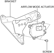
AIRFLOW MODE ACTUATOR INSTALLATION [MANUAL AIR CONDITIONER (E)]
id0740a28089y4
L.H.D.
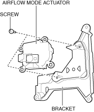
1. Install the airflow mode actuator to the bracket.
am3zzw00021387
|
2. Install the screws.
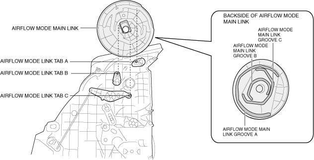
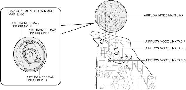
3. Align the following airflow mode link tabs with the airflow mode main link grooves and install the airflow mode main link.
am3zzw00032052
|
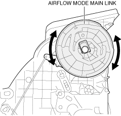
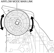
4. Move the airflow mode main link in the direction shown in the figure and verify that it rotates smoothly.
am3zzw00021389
|
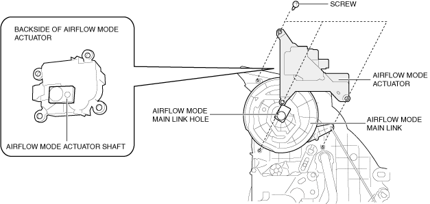
5. Align the airflow mode main link hole with the shape of the airflow mode actuator shaft, and install the airflow mode actuator.
am3zzw00028284
|
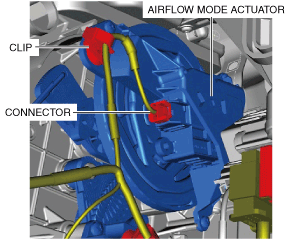
6. Install the screws.
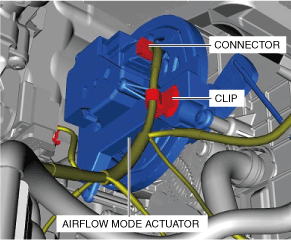
7. Install the clip.
am3zzw00028285
|
8. Connect the connector.
9. Install the following parts:
10. Connect the negative battery terminal. (See NEGATIVE BATTERY TERMINAL DISCONNECTION/CONNECTION [(E)].)
R.H.D.
1. Install the airflow mode actuator to the bracket.
am3zzw00028286
|
2. Install the screws.
3. Align the following airflow mode link tabs with the airflow mode main link grooves and install the airflow mode main link.
am3zzw00028287
|
4. Move the airflow mode main link in the direction shown in the figure and verify that it rotates smoothly.
am3zzw00028288
|
5. Align the airflow mode main link hole with the shape of the airflow mode actuator shaft, and install the airflow mode actuator.
am3zzw00028289
|
6. Install the screws.
7. Install the clip.
am3zzw00028290
|
8. Connect the connector.
9. Install the following parts:
10. Connect the negative battery terminal. (See NEGATIVE BATTERY TERMINAL DISCONNECTION/CONNECTION [(E)].)