 |
am3zzw00022955
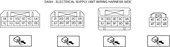
DASH-ELECTRICAL SUPPLY UNIT INSPECTION [MANUAL AIR CONDITIONER (E)]
id0740a28205y4
1. Disconnect the negative battery terminal and wait for 1 min or more. (See NEGATIVE BATTERY TERMINAL DISCONNECTION/CONNECTION [(E)].)
2. Remove the following parts:
3. Connect the negative battery terminal.
4. Switch the ignition ON (engine off or on).
5. Connect the negative (-) lead of the tester to body ground.
6. Insert the positive (+) lead of the tester into each dash-electrical supply unit terminal and measure the voltage according to the terminal voltage table.
Terminal Voltage Table (Reference)
am3zzw00022955
|
|
Terminal |
Signal name |
Connected to |
Measurement condition |
Voltage (V) |
Inspection item (s) |
|
|---|---|---|---|---|---|---|
|
1A
|
Foot light*1
|
Foot light control
|
Foot light ON
|
1.0 or less
|
• Related wiring harness
|
|
|
Foot light off
|
B+
|
|||||
|
1B
|
—
|
—
|
—
|
—
|
—
|
|
|
1C
|
—
|
—
|
—
|
—
|
—
|
|
|
1D
|
GND
|
Body ground
|
Under any condition
|
Approx. 0
|
• GND point
• Related wiring harness
|
|
|
1E
|
IG
|
F47 15 A fuse
|
Switch the ignition ON (engine off or on)
|
B+
|
• Related wiring harness
• F47 15 A fuse
|
|
|
Switch the ignition off
|
1.0 or less
|
|||||
|
1F
|
—
|
—
|
—
|
—
|
—
|
|
|
1G
|
+B
|
F16 15 A fuse
|
Under any condition
|
B+
|
• Related wiring harness
• F16 15 A fuse
|
|
|
1H
|
—
|
—
|
—
|
—
|
—
|
|
|
1I
|
HS_CAN_L
|
CAN related module
|
Because this terminal is for communication, integrity determination by terminal voltage is not possible.
|
• Related wiring harness
|
||
|
1J
|
HS_CAN_L
|
CAN related module
|
Because this terminal is for communication, integrity determination by terminal voltage is not possible.
|
• Related wiring harness
|
||
|
1K
|
HS_CAN_H
|
CAN related module
|
Because this terminal is for communication, integrity determination by terminal voltage is not possible.
|
• Related wiring harness
|
||
|
1L
|
HS_CAN_H
|
CAN related module
|
Because this terminal is for communication, integrity determination by terminal voltage is not possible.
|
• Related wiring harness
|
||
|
2A
|
—
|
—
|
—
|
—
|
—
|
|
|
2B
|
LIN1
|
• Air mix actuator
• Airflow mode actuator
• Air intake actuator
• PTC Heater *2
|
Because this terminal is for communication, integrity determination by terminal voltage is not possible.
|
• Related wiring harness
|
||
|
2C
|
—
|
—
|
—
|
—
|
—
|
|
|
2D
|
—
|
—
|
—
|
—
|
—
|
|
|
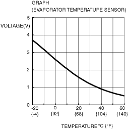
2E
|
Evaporator temperature sensor input
|
Evaporator temperature sensor
|
Compared with temperature detected by evaporator temperature sensor
|
Refer to graph
|
• Related wiring harness
|
|
|
2F
|
—
|
—
|
—
|
—
|
—
|
|
|
2G
|
Sensor GND
|
Evaporator temperature sensor
|
Under any condition
|
1.0 or less
|
• Related wiring harness
|
|
|
2H
|
GND_HVAC_1
|
• Air mix actuator
• Airflow mode actuator
• Air intake actuator
|
Under any condition
|
1.0 or less
|
• Related wiring harness
|
|
|
2I
|
—
|
—
|
—
|
—
|
—
|
|
|
2J
|
IG_HVAC_1
|
• Air mix actuator
• Airflow mode actuator
• Air intake actuator
• PTC heater *2
|
Switch the ignition ON (engine off or on)
|
B+
|
• Related wiring harness
|
|
|
Switch the ignition off
|
B+ / 1.0 or less *7
|
|||||
|
3A
|
HS_CAN_H
|
CAN related module
|
Because this terminal is for communication, integrity determination by terminal voltage is not possible.
|
• Related wiring harness
|
||
|
3B
|
HS_CAN_L
|
CAN related module
|
Because this terminal is for communication, integrity determination by terminal voltage is not possible.
|
• Related wiring harness
|
||
|
3C
|
—
|
—
|
—
|
—
|
—
|
|
|
3D
|
—
|
—
|
—
|
—
|
—
|
|
|
3E
|
—
|
—
|
—
|
—
|
—
|
|
|
3F
|
—
|
—
|
—
|
—
|
—
|
|
|
3G*8
|
Mode switch input *3
|
Drive selection switch
|
Ignition ON
|
Pressed to SPORT side (forward)
|
1.0 or less
|
• Related wiring harness
|
|
Pressed to OFF side (backward)
|
8.0
|
|||||
|
Not pressed
|
9.0
|
|||||
|
3G*9
|
Mode switch input *3
|
Drive selection switch
|
Ignition ON
|
Pressed to SPORT side (forward)
|
8.0
|
• Related wiring harness
|
|
Pressed to OFF side (backward)
|
1.0 or less
|
|||||
|
Not pressed
|
9.0
|
|||||
|
3H
|
Buckle switch input
|
Driver-side buckle switch
|
Ignition ON
|
Driver-side front buckle fastened
|
B+
|
• Related wiring harness
|
|
Driver-side front buckle unfastened
|
1.0 or less
|
|||||
|
3I
|
—
|
—
|
—
|
—
|
—
|
|
|
3J
|
LIN2
|
Seat warmer control unit *4 / Position memory control module *5 / Heated steering wheel control unit *6
|
Because this terminal is for communication, integrity determination by terminal voltage is not possible.
|
• Related wiring harness
|
||
|
4A
|
Motor operation (-)
|
Blower motor
|
Switch the ignition off
|
1.0 or less
|
• Related wiring harness
• Blower motor
|
|
|
Fan stopped (Switch the ignition ON (engine off or on))
|
B+
|
|||||
|
4B
|
—
|
—
|
—
|
—
|
—
|
|
|
4C
|
Blower motor GND
|
Body ground
|
Under any condition
|
Approx. 0
|
• GND point
• Related wiring harness
|
|
|
4D
|
—
|
—
|
—
|
—
|
—
|
|
|
4E
|
Motor operation (+)
|
Blower motor
|
Switch the ignition off
|
1.0 or less
|
• Related wiring harness
• Blower motor
|
|
|
Switch the ignition ON (engine off or on)
|
B+
|
|||||
|
4F
|
B+
|
Blower relay
|
Switch the ignition off
|
1.0 or less
|
• Related wiring harness
|
|
|
Switch the ignition ON (engine off or on)
|
B+
|
|||||
 |