AUTO LEVELING CONTROL MODULE REMOVAL/INSTALLATION [(E)]
AUTO LEVELING CONTROL MODULE REMOVAL/INSTALLATION [(E)]
id0918008055x2
Note
• The auto leveling control module reads the vehicle attitude angle information and records the vehicle attitude angle while it is unoccupied when the headlight auto leveling system initial setting is performed after the auto leveling control module is replaced.
• Even if the battery is disconnected, the unoccupied vehicle attitude angle recorded by the auto leveling control module is not erased.
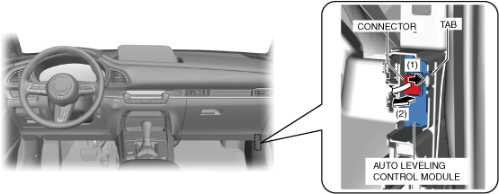
3. While pressing tab of the bracket in the direction of arrows (1) shown in the figure, pull the auto leveling control module connector in the direction of arrow (2) to pull out the auto leveling control module from the bracket.
ac30zw00002315
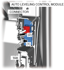
4. While pressing tab of the bracket in the direction of arrows (1) shown in the figure, pull the auto leveling control module connector in the direction of arrow (2) to pull out the auto leveling control module from the bracket.
ac30zw00002316
5. Disconnect the connector and remove the auto leveling control module.
6. Install in the reverse order of removal.
7. If the auto leveling control module is replaced, perform the following procedure.
(1) Switch the ignition ON (engine off) to complete the global central configuration (GCC) for the auto leveling control module.
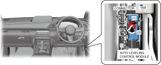
3. While pressing tab of the bracket in the direction of arrows (1) shown in the figure, pull the auto leveling control module connector in the direction of arrow (2) to pull out the auto leveling control module from the bracket.
ac30zw00002317
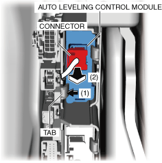
4. While pressing tab of the bracket in the direction of arrows (1) shown in the figure, pull the auto leveling control module connector in the direction of arrow (2) to pull out the auto leveling control module from the bracket.
ac30zw00002318
5. Disconnect the connector and remove the auto leveling control module.
6. Install in the reverse order of removal.
7. If the auto leveling control module is replaced, perform the following procedure.
(1) Switch the ignition ON (engine off) to complete the global central configuration (GCC) for the auto leveling control module.