DTC P056E:00 [PCM (SKYACTIV-X)]
id0102u9135200
Details On DTCs
Description |
Supercharger: Function malfunction due to cold temperatures |
||
---|---|---|---|
Detection condition
|
Determination conditions
|
• The control current of the supercharger clutch is the specified value or more and the supercharger speed sensor output value is the specified value or less.
|
|
Preconditions
|
• Supercharger unit temperature (estimated value based on intake air temperature) is specified value or less
• Engine speed is specified value or more
|
||
Drive cycle
|
• 1
|
||
Self test type
|
• CMDTC self test
|
||
Sensor used
|
• Supercharger speed sensor
• Supercharger clutch
• IAT Sensor No.2
|
||
Fail-safe function
|
• Inhibits the boost system.
• Stops the EGR control.
|
||
Vehicle status when DTCs are output
|
• Engine output is restricted.
• The PCM stores DTCs P056E:00 and P2578:00 at the same time.
|
||
Possible cause
|
• Rotors in supercharger are stuck (because moisture in supercharger is frozen at 0 °C {0 °F} or less)
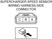
• Supercharger speed sensor connectors or terminals malfunction
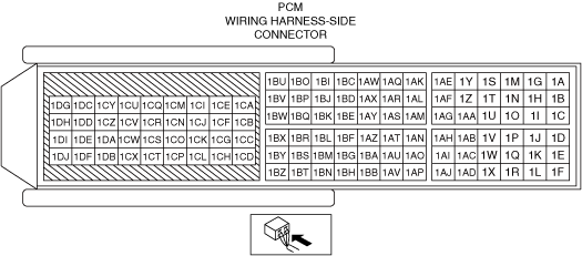
• PCM connector or terminals malfunction
• Supercharger malfunction
• Supercharger speed sensor malfunction
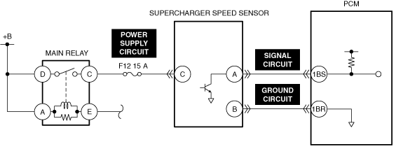
• F12 15 A fuse malfunction
• Short to ground or open circuit in supercharger speed sensor power supply circuit
• Short to ground circuit in supercharger speed sensor signal circuit
• Open circuit in any of the following supercharger speed sensor circuits.
• Short to power supply in any of the following supercharger speed sensor circuits.
• PCM malfunction
|
||
![]() |
|||
![]() |
|||
![]() |
Function Explanation (DTC Detection Outline)
Repeatability Verification Procedure
1. Start the engine and warm it up completely.
PID Item/Simulation Item Used In Diagnosis
PID/DATA monitor item table
PIDs |
Reference |
---|---|
AIR_BYPASS_VLV_POS_DSD
|
|
ENG_RPM_DSD
|
|
MAP
|
|
SUPER_CHARGER_IN_PRES_ACT
|
|
SUPER_CHARGER_RPM
|
Function Inspection Using M-MDS
Step |
Inspection |
Results |
Action |
---|---|---|---|
1
|
PURPOSE: VERIFY RELATED REPAIR INFORMATION OR SERVICE INFORMATION AVAILABILITY
• Verify related Service Bulletins, on-line repair information, or Service Information availability.
• Is any related Information available?
|
Yes
|
Perform repair or diagnosis according to the available information.
• If the vehicle is not repaired, go to the next step.
|
No
|
Go to the next step.
|
||
2
|
PURPOSE: RECORD VEHICLE STATUS WHEN DTC WAS DETECTED TO UTILIZE WITH REPEATABILITY VERIFICATION
• Record the freeze frame data/snapshot data.
|
—
|
Go to the next step.
|
3
|
PURPOSE: VERIFY IF CAUSE IS FREEZING
• Clear the DTC recorded in the memory.
(See CLEARING DTC.)
• Replicate the vehicle conditions at the time the DTC was detected using the following procedure.
• Perform the DTC inspection for the PCM.
(See DTC INSPECTION.)
• Is the same Pending DTC present?
|
Yes
|
DTC troubleshooting completed.
|
No
|
P25EC:00 OR P25ED:00 is displayed
• Repair the malfunctioning location according to the applicable DTC troubleshooting.
OTHER DTCS are displayed
• Go to the next step.
|
||
4
|
PURPOSE: VERIFY CONNECTOR CONNECTIONS
• Start the engine.
• Access the SUPER_CHARGER_RPM PID using the M-MDS.
(See PID/DATA MONITOR INSPECTION.)
• Does the PID value fluctuate when the following connectors are shaken?
|
Yes
|
Repair or replace the applicable wiring harness or connector parts.
Go to the next step.
|
No
|
Go to the next step.
|
||
5
|
PURPOSE: DETERMINE IF MALFUNCTION IS CAUSED BY SUPERCHARGER
• Start the engine.
• Display the following PID and simulation items using the M-MDS.
• Perform the following procedure.
• Did the engine stall?
|
Yes
|
Replace the supercharger.
Go to Troubleshooting Diagnostic Procedure to perform the repair completion verification.
|
No
|
Go to the next step.
|
||
6
|
PURPOSE: DETERMINE IF MALFUNCTION IS CAUSED BY SUPERCHARGER CLUTCH
• Perform the following procedure.
• Verify the value of the PID SUPER_CHARGER_RPM.
• Is the value 0?
|
Yes
|
Go to the next step.
|
No
|
Replace the supercharger (built into supercharger clutch) because the supercharger speed sensor is normal.
Go to Troubleshooting Diagnostic Procedure to perform the repair completion verification.
|
||
7
|
PURPOSE: DETERMINE IF MALFUNCTION IS CAUSED BY SUPERCHARGER SPEED SENSOR
• Perform the following procedure.
• Record the values of the PID SUPER_CHARGER_IN_PRES_ACT and MAP, and calculate the difference.
• When comparing the value calculated in Step 5 with the value calculated in Step 7, is the difference 5 kPa {0.05 kgf/cm2, 0.7 psi} or more?
|
Yes
|
Replace the supercharger.
Go to Troubleshooting Diagnostic Procedure to perform the repair completion verification.
|
No
|
Replace the supercharger speed sensor.
Go to Troubleshooting Diagnostic Procedure to perform the procedure from Step 1.
|
Troubleshooting Diagnostic Procedure
Step |
Inspection |
Results |
Action |
---|---|---|---|
1
|
PURPOSE: INSPECT F12 15 A FUSE
• Remove the F12 15 A fuse.
• Inspect the F12 15 A fuse.
• Is the fuse normal?
|
Yes
|
Reinstall the F12 15 A fuse, then go to the next step.
|
No
|
Replace the F12 15 A fuse and perform the repair completion verification.
|
||
2
|
PURPOSE: INSPECT SUPERCHARGER SPEED SENSOR POWER SUPPLY CIRCUIT FOR SHORT TO GROUND AND OPEN CIRCUIT
• Inspect the power supply circuit for an open circuit and short to ground.
(See CIRCUIT INSPECTION.)
• Is the circuit normal?
|
Yes
|
Go to the next step.
|
No
|
Repair or replace the malfunctioning location and perform the repair completion verification.
|
||
3
|
PURPOSE: INSPECT PCM CONNECTOR FOR MALFUNCTION
• Inspect the applicable connector and terminal.
(See CONNECTOR INSPECTION.)
• Are the connector and terminal normal?
|
Yes
|
Go to the next step.
|
No
|
Repair or replace the malfunctioning location and perform the repair completion verification.
|
||
4
|
PURPOSE: INSPECT SUPERCHARGER SPEED SENSOR SIGNAL CIRCUIT FOR SHORT TO GROUND
• Inspect the applicable circuit for a short to ground.
(See CONNECTOR INSPECTION.)
• Is the circuit normal?
|
Yes
|
Go to the next step.
|
No
|
Repair or replace the malfunctioning location and perform the repair completion verification.
|
||
5
|
PURPOSE: INSPECT SUPERCHARGER SPEED SENSOR SIGNAL CIRCUIT AND GROUND CIRCUIT FOR OPEN CIRCUIT
• Inspect the applicable circuit for open circuit.
(See CONNECTOR INSPECTION.)
• Is the circuit normal?
|
Yes
|
Go to the next step.
|
No
|
Repair or replace the malfunctioning location and perform the repair completion verification.
|
||
6
|
PURPOSE: INSPECT SUPERCHARGER SPEED SENSOR SIGNAL CIRCUIT AND GROUND CIRCUIT FOR SHORT TO POWER SUPPLY
• Inspect the applicable circuit for a short to power supply.
(See CONNECTOR INSPECTION.)
• Is the circuit normal?
|
Yes
|
Go to the next step.
|
No
|
Repair or replace the malfunctioning location and perform the repair completion verification.
|
||
7
|
PURPOSE: INSPECT SUPERCHARGER SPEED SENSOR FOR MALFUNCTION
• Inspect the applicable part.
• Is the part normal?
|
Yes
|
Go to the next step.
|
No
|
Repair or replace the malfunctioning location and perform the repair completion verification.
|
||
Repair completion verification 1
|
VERIFY THAT VEHICLE IS REPAIRED
• Install/connect the part removed/disconnected during the troubleshooting procedure.
• Clear the DTC recorded in the memory.
(See CLEARING DTC.)
• Replicate the vehicle conditions at the time the DTC was detected using the following procedure.
• Perform the DTC inspection for the PCM.
(See DTC INSPECTION.)
• Is the same Pending DTC present?
|
Yes
|
Refer to the controller area network (CAN) malfunction diagnosis flow to inspect for a CAN communication error.
If the CAN communication is normal, perform the diagnosis from Step 1.
• If the malfunction recurs, replace the PCM, then go to the next step.
|
No
|
Go to the next step.
|
||
Repair completion verification 2
|
VERIFY IF OTHER DTCs DISPLAYED
• Perform the DTC inspection.
(See DTC INSPECTION.)
• Are any other DTCs displayed?
|
Yes
|
Repair the malfunctioning location according to the applicable DTC troubleshooting.
|
No
|
DTC troubleshooting completed.
|