SUPERCHARGER REMOVAL/INSTALLATION [SKYACTIV-X 2.0]
Home
Replacement part
Gasket
Quantity: 2
Location of use: Inlet pipe
Gasket
Quantity: 1
Location of use: Air bypass valve
Gasket
Quantity: 1
Location of use: Supercharger
Vacuum hose
Quantity: 2
Location of use: EGR pressure sensor
Clamp
Quantity: 1
Location of use: Supercharger component
Clamp
Quantity: 1
Location of use: EGR pipe
O-ring
Quantity: 2
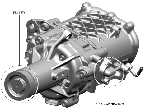
Location of use: Pipe connector
—
—
Caution
• If the intake-air system, exhaust system, or the engine is damaged, fragments of the damaged part may be remaining in the intake-air system or exhaust system. If the supercharger is replaced without removing fragments of the damaged part, it could cause supercharger damage or malfunction. Before replacing the supercharger, verify that no fragments remain in the parts to be reused.
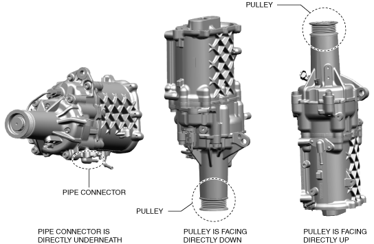
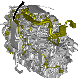
• When storing the supercharger, place it in the direction shown in the following figure to prevent oil leakage.
• Because oil leakage may occur when the supercharger is stored in any of the directions shown in the figure, be careful when storing it.
1. Disconnect the negative battery terminal. (See NEGATIVE BATTERY TERMINAL DISCONNECTION/CONNECTION [(E)]
2. Remove the engine cover. (See ENGINE COVER REMOVAL/INSTALLATION [SKYACTIV-X 2.0]
3. Remove the following parts. (See SIDE WALL REMOVAL/INSTALLATION [SKYACTIV-X 2.0]
• Right wall
• Rear wall
• Left wall (rear)
4. Remove the following parts as a single unit. (See AIR CLEANER REMOVAL/INSTALLATION [SKYACTIV-X 2.0]
• Air hose
• Air cleaner element
• Air cleaner case
• Fresh-air duct
• Left wall (front)
5. Remove the resonance chamber. (See AIR CLEANER REMOVAL/INSTALLATION [SKYACTIV-X 2.0]
6. Remove the battery and the battery tray. (See BATTERY REMOVAL/INSTALLATION [SKYACTIV-X 2.0]
7. Remove front under cover No.1. (See FRONT UNDER COVER No.1 REMOVAL/INSTALLATION
8. Remove front under cover No.2. (See FRONT UNDER COVER No.2 REMOVAL/INSTALLATION
9. Remove the front splash shield (RH). (See SPLASH SHIELD REMOVAL/INSTALLATION
10. Drain the engine coolant. (See ENGINE COOLANT REPLACEMENT [SKYACTIV-X 2.0]
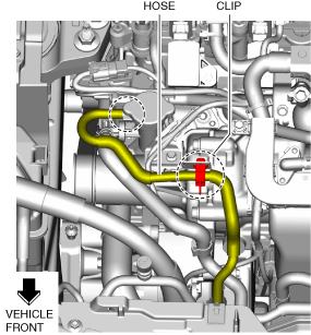
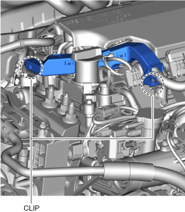
11. Disconnect the hose and clip shown in the figure.
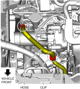
12. Disconnect the hose and clip shown in the figure.
13. Remove the coolant reserve tank. (See COOLANT RESERVE TANK REMOVAL/INSTALLATION [SKYACTIV-X 2.0]
14. Remove the water-cooled charge air cooler reserve tank. (See WATER-COOLED CHARGE AIR COOLER RESERVE TANK REMOVAL/INSTALLATION [SKYACTIV-X 2.0]
15. Remove the cooling fan motor. (See COOLING FAN MOTOR REMOVAL/INSTALLATION [SKYACTIV-X 2.0]
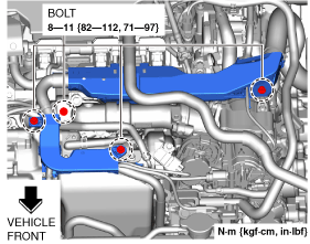
16. Remove the bolts shown in the figure.
17. Disconnect the clips shown in the figure.
18. Disconnect the starter terminal S connector. (See STARTER REMOVAL/INSTALLATION [SKYACTIV-X 2.0]
19. Disconnect the integrated starter generator (ISG) terminal B cable. (See INTEGRATED STARTER GENERATOR (ISG) REMOVAL/INSTALLATION [SKYACTIV-X 2.0]
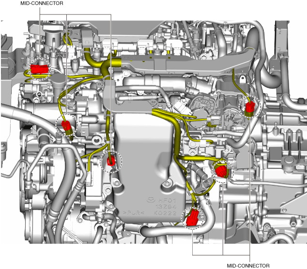
20. Disconnect the mid-connectors shown in the figure.
21. Disconnect the connectors of the following parts:
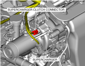
22. Disconnect the supercharger clutch connector.
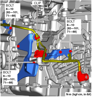
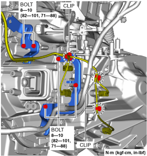
23. Disconnect the clip and remove the bolts shown in the figure. (ATX)
24. Disconnect the clips and remove the bolts shown in the figure. (MTX)
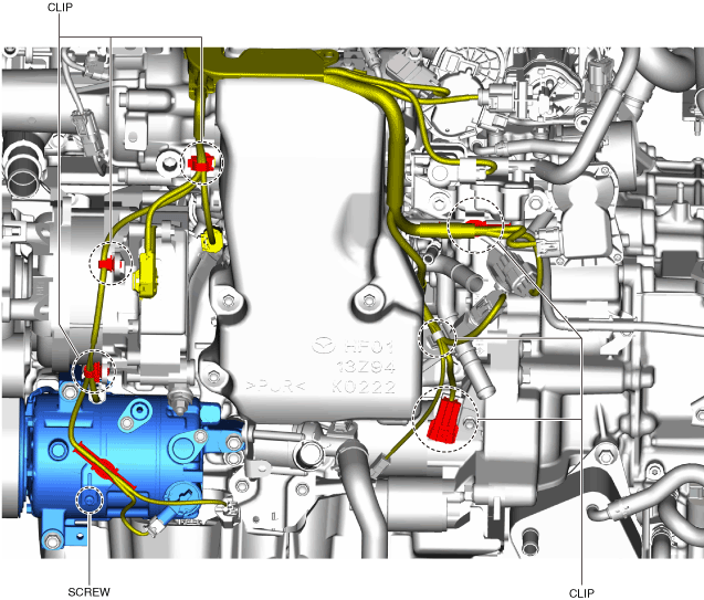
25. Disconnect the clips and remove the screw shown in the figure.
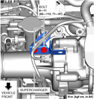
26. Remove the bolts shown in the figure.
27. Set the wiring harness aside as shown in the figure.
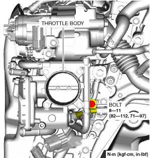
28. Remove the bolt shown in the figure.
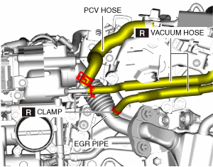
29. Disconnect the hoses shown in the figure.
30. Remove the purge solenoid valve component. (See PURGE SOLENOID VALVE REMOVAL/INSTALLATION [SKYACTIV-X 2.0]
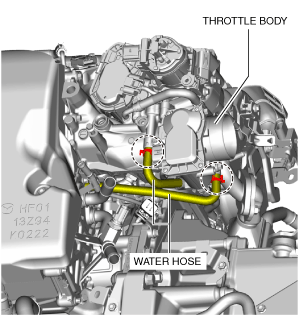
31. Disconnect the water hoses shown in the figure.
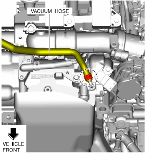
32. Disconnect the vacuum hose shown in the figure.
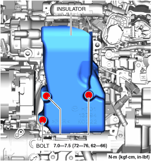
33. Remove the insulator shown in the figure.
34. Remove air pipe No.1. (See AIR PIPE REMOVAL/INSTALLATION [SKYACTIV-X 2.0]
35. Remove the water pump drive belt from the supercharger and set it aside. (See DRIVE BELT REMOVAL/INSTALLATION [SKYACTIV-X 2.0]
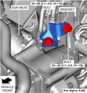
36. Remove the bracket shown in the figure.
37. Remove the EGR pipe. (See EGR PIPE REMOVAL/INSTALLATION [SKYACTIV-X 2.0]
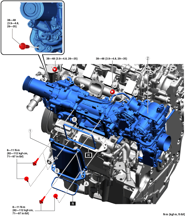
38. Remove using the procedure shown in the figure.
39. Install in the reverse order of removal.
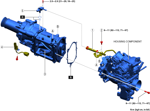
Step 1
1
Inlet pipe
2
Supercharger component
Step 2
1
Vacuum hose
2
Vacuum pipe bracket bolt
3
Supercharger
4
Short-cord
5
Pipe connector
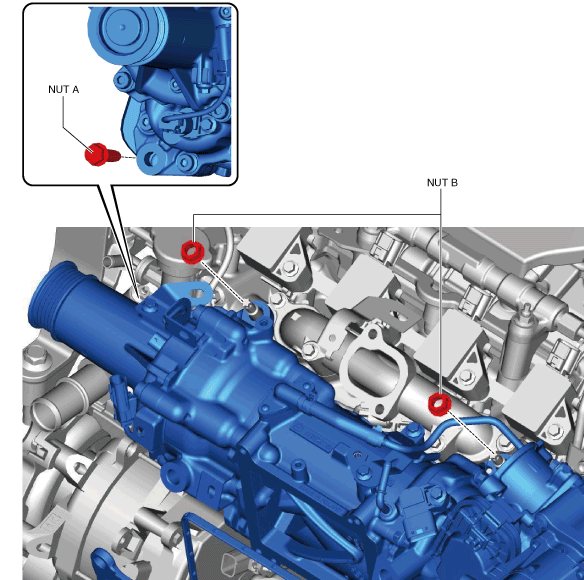
1. Temporarily tighten the bolt shown in the figure.
2. Tighten the nuts and bolt in the order shown in the figure.
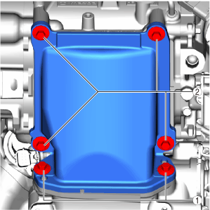
1. Tighten the bolts in the order shown in the figure.
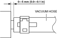
1. Install the vacuum hose as shown in the figure.