DTC P2502:00 [PCM (SKYACTIV-X)]
id0102u9709500
Details On DTCs
Description |
Generator system: Voltage malfunction |
||
---|---|---|---|
Detection condition
|
Determination conditions
|
• If any of the following conditions is met:
Condition A
Condition B
Condition C
Condition D
|
|
Preconditions
|
Condition A
• While engine is running
Condition B or C
• CAN communication between PCM and Mazda M Hybrid battery is normal
Condition D
• CAN communication between PCM and DC-DC converter (Mazda M Hybrid) is normal
|
||
Malfunction determination period
|
Condition A or D
• 5 s period
Condition B
• 3 s period
Condition C
• 10% or less: 3 s period
• 95% or more: 30 s period
|
||
Drive cycle
|
• 1
|
||
Self test type
|
• CMDTC self test
|
||
Sensor used
|
• PCM
• Mazda M Hybrid battery
|
||
Fail-safe function
|
Condition A
• Not applicable
Condition B, C (95% or more), or D
• Stops power supply by step-down circuit in DC-DC converter (Mazda M Hybrid).
• Stops power generation by integrated starter generator (ISG).
• Turns off contactor for Mazda M Hybrid battery and supply power to vehicle electrical devices (12 V power supply) from battery.
Condition C (10% or less)
• Stops power supply by step-down circuit in DC-DC converter (Mazda M Hybrid).
|
||
Vehicle status when DTCs are output
|
• If the vehicle continues to be driven while the DTC is detected the battery will be depleted.
• The following vehicle conditions differ depending on the type of malfunction:
|
||
Possible cause
|
• DTCs are stored in the following modules.
• Poor connection of the following parts:
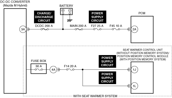
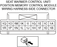
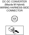
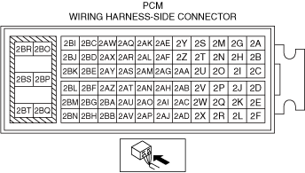
• Connector or terminal malfunction of the following parts:
• Mazda M Hybrid battery malfunction
• Mazda M Hybrid battery discharge caused by leaving vehicle for long periods
• Temporary increase in Mazda M Hybrid battery temperature
• Battery malfunction
• Short to ground, short to power supply, or open circuit in DC-DC converter (Mazda M Hybrid) charge/discharge circuit
• Short to ground, short to power supply, or open circuit in seat warmer control unit power supply circuit (with seat warmer system and without position memory system)
• Short to ground, short to power supply, or open circuit in position memory control module power supply circuit (with position memory system)
• Short to ground, short to power supply, or open circuit in PCM power supply circuit
• PCM malfunction
|
||
![]() |
|||
![]() |
![]() |
||
![]() |
![]() |
Function Explanation (DTC Detection Outline)
Repeatability Verification Procedure
PID Item/Simulation Item Used In Diagnosis
PID/DATA monitor item table
PIDs |
Reference |
---|---|
BATT_SOC
|
|
BATT_TEMP_1
|
|
BATT_TEMP_2
|
|
CELL_VOLT_1
|
|
CELL_VOLT_2
|
|
CELL_VOLT_3
|
|
CELL_VOLT_4
|
|
CELL_VOLT_5
|
|
CELL_VOLT_6
|
|
CELL_VOLT_7
|
|
CELL_VOLT_8
|
|
CELL_VOLT_9
|
|
HV_EV_BATT_SOC
|
Function Inspection Using M-MDS
Step |
Inspection |
Results |
Action |
---|---|---|---|
1
|
PURPOSE: VERIFY RELATED REPAIR INFORMATION OR SERVICE INFORMATION AVAILABILITY
• Verify related Service Bulletins, on-line repair information, or Service Information availability.
• Is any related Information available?
|
Yes
|
Perform repair or diagnosis according to the available information.
• If the vehicle is not repaired, go to the next step.
|
No
|
Go to the next step.
|
||
2
|
PURPOSE: RECORD VEHICLE STATUS WHEN DTC WAS DETECTED TO UTILIZE WITH REPEATABILITY VERIFICATION
• Record the freeze frame data/snapshot data.
|
—
|
Go to the next step.
|
3
|
PURPOSE: INSPECT FOR OTHER RELATED DTCs
• Perform the DTC inspection for the following modules.
(See DTC INSPECTION.)
• Are any DTCs displayed?
|
Yes
|
Repair the malfunctioning location according to the applicable DTC troubleshooting.
|
No
|
Go to the next step.
|
||
4
|
PURPOSE: INSPECT FOR OTHER RELATED DTCs
• Perform the DTC inspection for the PCM.
(See DTC INSPECTION.)
• Are any other of the following DTCs displayed?
|
Yes
|
Repair the malfunctioning location according to the applicable DTC troubleshooting.
(See DTC TABLE [PCM (SKYACTIV-X)].)
|
No
|
Go to the next step.
|
||
5
|
PURPOSE: INSPECT FOR OTHER RELATED DTCs
• Access the Mazda M Hybrid battery PID HV_EV_BATT_SOC using the M-MDS.
(See PID/DATA MONITOR INSPECTION.)
• Is the PID value 10% or less or 95% or more?
|
Yes
|
10% or less:
• Go to Step 7.
95% or more:
• Go to the next step.
Minus value:
• Replace the Mazda M Hybrid battery, then go to Step 8.
|
No
|
Go to Step 9.
|
||
6
|
PURPOSE: VERIFY IF MALFUNCTION IS CAUSED BY Mazda M Hybrid BATTERY OVERCHARGE
• Perform the following procedure to discharge the Mazda M Hybrid battery until the PID HV_EV_BATT_SOC value is 95% or less.
• Perform the DTC inspection for the PCM.
(See DTC INSPECTION.)
• Is the same Pending DTC present?
|
Yes
|
Replace the Mazda M Hybrid battery, then go to Step 8.
|
No
|
Intermittent concern exists.
• Go to Troubleshooting Diagnostic Procedure to perform the repair completion verification.
|
||
7
|
PURPOSE: INSPECT VOLTAGES OF EACH CELL FOR Mazda M Hybrid BATTERY
• Access the following Mazda M Hybrid battery PIDs using the M-MDS:
(See PID/DATA MONITOR INSPECTION.)
• Is there a PID value of 1.8 V or less?
|
Yes
|
Replace the Mazda M Hybrid battery, then go to Step 8.
|
No
|
Intermittent concern exists.
• Explain to the customer that the function was stopped due to Mazda M Hybrid battery discharge.
• Perform the following procedure to charge the Mazda M Hybrid battery until the PID HV_EV_BATT_SOC value reaches 20% or more.
• Go to Troubleshooting Diagnostic Procedure to perform the repair completion verification.
|
||
8
|
PURPOSE: VERIFY Mazda M Hybrid BATTERY DTCs
• Perform the DTC inspection for the Mazda M Hybrid battery.
(See DTC INSPECTION.)
• Are any DTCs displayed?
|
Yes
|
Repair the malfunctioning location according to the applicable DTC troubleshooting.
|
No
|
Go to Troubleshooting Diagnostic Procedure to perform the repair completion verification.
|
||
9
|
DETERMINE IF MALFUNCTION CAUSE IS BATTERY RELATED CIRCUIT OR OTHER PART
• Access the Mazda M Hybrid battery PID BATT_SOC using the M-MDS.
(See PID/DATA MONITOR INSPECTION.)
• Is the charged capacity of the Mazda M Hybrid battery normal?
|
Yes
|
Go to the next step.
|
No
|
Go to Troubleshooting Diagnostic Procedure to perform the procedure from Step 1.
|
||
10
|
PURPOSE: VERIFY WHETHER MALFUNCTION IS PRESENT OR PAST
• Perform the DTC inspection for the PCM.
(See DTC INSPECTION.)
• Is DTC P2502:00 a present malfunction?
|
Yes
|
Go to the next step.
|
No
|
Go to Step 12.
|
||
11
|
PURPOSE: VERIFY IF MALFUNCTION IS CAUSED BY INCREASE IN Mazda M Hybrid BATTERY TEMPERATURE
• Access the following Mazda M Hybrid battery PIDs using the M-MDS:
(See PID/DATA MONITOR INSPECTION.)
• Is the PID value 90 °C {194 °F} or more?
|
Yes
|
Intermittent concern exists.
• Explain to the customer that the malfunction is caused by an increase in the Mazda M Hybrid battery temperature. (This can be used if temperature decreases)
• Go to Troubleshooting Diagnostic Procedure to perform the repair completion verification.
|
No
|
Go to the next step.
|
||
12
|
PURPOSE: INSPECT FOR OTHER RELATED DTCs
• Perform the DTC inspection for the following modules.
(See DTC INSPECTION.)
• Are any other of the DTC P2502:00 displayed?
|
Yes
|
Repair the malfunctioning location according to the applicable DTC troubleshooting.
(See DTC TABLE [PCM (SKYACTIV-X)].)
|
No
|
Intermittent concern exists.
• Go to Troubleshooting Diagnostic Procedure to perform the repair completion verification.
|
Troubleshooting Diagnostic Procedure
Step |
Inspection |
Results |
Action |
---|---|---|---|
1
|
PURPOSE: VERIFY IF POOR CONNECTION OF DC-DC CONVERTER (Mazda M Hybrid) AFFECTS DIAGNOSTIC RESULTS
• Inspect the connection condition (part installation condition, connector connection condition) for the DC-DC converter (Mazda M Hybrid).
• Is the connection condition (part installation condition, connector connection condition) for each part normal?
|
Yes
|
Go to the next step.
|
No
|
Connect each part or the connector correctly.
Recharge or replace the battery then perform the repair completion verification.
(See BATTERY RECHARGING [(E)].)
|
||
2
|
PURPOSE: INSPECT DC-DC CONVERTER (Mazda M Hybrid) CONNECTOR FOR MALFUNCTION
• Inspect the applicable connector and terminal.
(See CONNECTOR INSPECTION.)
• Are the connector and terminal normal?
|
Yes
|
Go to the next step.
|
No
|
Repair or replace the malfunctioning location.
Recharge or replace the battery then perform the repair completion verification.
(See BATTERY RECHARGING [(E)].)
|
||
3
|
PURPOSE: INSPECT DC-DC CONVERTER (Mazda M Hybrid) CHARGE/DISCHARGE CIRCUIT FOR SHORT TO GROUND, SHORT TO POWER SUPPLY, AND OPEN CIRCUIT
• Inspect the charge/discharge circuit for a short to ground, short to power supply, and open circuit.
(See CIRCUIT INSPECTION.)
• Is the circuit normal?
|
Yes
|
Without seat warmer system:
• Go to Step 7.
With seat warmer system:
• Go to the next step.
|
No
|
Repair or replace the malfunctioning location.
Recharge or replace the battery then perform the repair completion verification.
(See BATTERY RECHARGING [(E)].)
|
||
4
|
PURPOSE: VERIFY IF POOR CONNECTION OF SEAT WARMER CONTROL UNIT (WITHOUT POSITION MEMORY SYSTEM)/POSITION MEMORY CONTROL MODULE (WITH POSITION MEMORY SYSTEM) AFFECTS DIAGNOSTIC RESULTS
• Inspect the connection condition (part installation condition, connector connection condition) for the seat warmer control unit (without position memory system)/position memory control module (with position memory system).
• Is the connection condition (part installation condition, connector connection condition) for each part normal?
|
Yes
|
Go to the next step.
|
No
|
Connect each part or the connector correctly.
Recharge or replace the battery then perform the repair completion verification.
(See BATTERY RECHARGING [(E)].)
|
||
5
|
PURPOSE: INSPECT SEAT WARMER CONTROL UNIT (WITHOUT POSITION MEMORY SYSTEM)/POSITION MEMORY CONTROL MODULE (WITH POSITION MEMORY SYSTEM) CONNECTOR FOR MALFUNCTION
• Inspect the applicable connector and terminal.
(See CONNECTOR INSPECTION.)
• Are the connector and terminal normal?
|
Yes
|
Go to the next step.
|
No
|
Repair or replace the malfunctioning location.
Recharge or replace the battery then perform the repair completion verification.
(See BATTERY RECHARGING [(E)].)
|
||
6
|
PURPOSE: INSPECT SEAT WARMER CONTROL UNIT (WITHOUT POSITION MEMORY SYSTEM)/POSITION MEMORY CONTROL MODULE (WITH POSITION MEMORY SYSTEM) POWER SUPPLY CIRCUIT FOR SHORT TO GROUND, SHORT TO POWER SUPPLY, AND OPEN CIRCUIT
• Inspect the power supply circuit for a short to ground, short to power supply, and open circuit.
(See CIRCUIT INSPECTION.)
• Is the circuit normal?
|
Yes
|
Go to the next step.
|
No
|
Repair or replace the malfunctioning location.
Recharge or replace the battery then perform the repair completion verification.
(See BATTERY RECHARGING [(E)].)
|
||
7
|
PURPOSE: VERIFY IF POOR CONNECTION OF BATTERY AFFECTS DIAGNOSTIC RESULTS
• Switch the ignition off.
• Inspect the connection condition (part installation condition, connector connection condition) for the battery.
• Is the connection condition (part installation condition, connector connection condition) for each part normal?
|
Yes
|
Go to the next step.
|
No
|
Connect each part or the connector correctly.
Recharge or replace the battery then perform the repair completion verification.
(See BATTERY RECHARGING [(E)].)
|
||
8
|
PURPOSE: VERIFY IF POOR CONNECTION OF PCM AFFECTS DIAGNOSTIC RESULTS
• Inspect the connection condition (part installation condition, connector connection condition) for the PCM.
• Is the connection condition (part installation condition, connector connection condition) for each part normal?
|
Yes
|
Go to the next step.
|
No
|
Connect each part or the connector correctly.
Recharge or replace the battery then perform the repair completion verification.
(See BATTERY RECHARGING [(E)].)
|
||
9
|
PURPOSE: INSPECT PCM CONNECTOR FOR MALFUNCTION
• Inspect the applicable connector and terminal.
(See CONNECTOR INSPECTION.)
• Are the connector and terminal normal?
|
Yes
|
Go to the next step.
|
No
|
Repair or replace the malfunctioning location.
Recharge or replace the battery then perform the repair completion verification.
(See BATTERY RECHARGING [(E)].)
|
||
10
|
PURPOSE: INSPECT PCM POWER SUPPLY CIRCUIT FOR SHORT TO GROUND, SHORT TO POWER SUPPLY, AND OPEN CIRCUIT
• Inspect the power supply circuit for a short to ground, short to power supply, and open circuit.
(See CIRCUIT INSPECTION.)
• Is the circuit normal?
|
Yes
|
Go to the next step.
|
No
|
Repair or replace the malfunctioning location.
Recharge or replace the battery then perform the repair completion verification.
(See BATTERY RECHARGING [(E)].)
|
||
11
|
PURPOSE: INSPECT FOR OTHER RELATED DTCs
• Perform the DTC inspection for the following modules.
(See DTC INSPECTION.)
• Are any other of the DTC P2502:00 displayed?
|
Yes
|
Repair the malfunctioning location according to the applicable DTC troubleshooting.
(See DTC TABLE [PCM (SKYACTIV-X)].)
|
No
|
Recharge or replace the battery then perform the repair completion verification.
(See BATTERY RECHARGING [(E)].)
|
||
Repair completion verification 1
|
PURPOSE: VERIFY THAT VEHICLE IS REPAIRED
• Install/connect the part removed/disconnected during the troubleshooting procedure.
• Clear the DTC recorded in the memory.
(See CLEARING DTC.)
• Replicate the vehicle conditions at the time the DTC was detected using the following procedure.
• Perform the DTC inspection for the PCM.
(See DTC INSPECTION.)
• Is the same Pending DTC present?
|
Yes
|
Refer to the controller area network (CAN) malfunction diagnosis flow to inspect for a CAN communication error.
If the CAN communication is normal, perform the diagnosis from Step 1.
• If the malfunction recurs, replace the PCM, then go to the next step.
|
No
|
Go to the next step.
|
||
Repair completion verification 2
|
PURPOSE: VERIFY IF OTHER DTCs DISPLAYED
• Perform the DTC inspection.
(See DTC INSPECTION.)
• Are any other DTCs displayed?
|
Yes
|
Repair the malfunctioning location according to the applicable DTC troubleshooting.
|
No
|
DTC troubleshooting completed.
|