Home

Mazdamanuals.com

ELECTRIC VARIABLE VALVE TIMING MOTOR/DRIVER REMOVAL/INSTALLATION [SKYACTIV-X 2.0]

ELECTRIC VARIABLE VALVE TIMING MOTOR/DRIVER REMOVAL/INSTALLATION [SKYACTIV-X 2.0]


 id0110hf808100

Replacement Part

O-ring
 
Quantity: 2
 
Location of use: Electric variable valve timing motor/driver

Warning
•  A hot engine can cause severe burns. Turn off the engine and wait until it is cool before removing the electric variable valve timing motor/driver.
Caution
•  Applying excessive force (100 N or more) to the electric variable valve timing motor/driver may cause a malfunction. When servicing, be careful not to apply excessive force to the electric variable valve timing motor/driver with other parts or tools.
•  Do not disassemble the electric variable valve timing motor/driver because it is a precision unit.

1.  Disconnect the negative battery terminal. (See NEGATIVE BATTERY TERMINAL DISCONNECTION/CONNECTION [(E)].)

2.  Remove the engine cover. (See ENGINE COVER REMOVAL/INSTALLATION [SKYACTIV-X 2.0].)

3.  Remove the following parts. (See SIDE WALL REMOVAL/INSTALLATION [SKYACTIV-X 2.0].)

•  Left wall (rear)
•  Rear wall

4.  Remove the following parts as a single unit: (See AIR CLEANER REMOVAL/INSTALLATION [SKYACTIV-X 2.0].)

•  Air cleaner cover
•  Air cleaner element
•  Air cleaner case
•  Air hose
•  Fresh-air duct

5.  Remove the battery tray and PCM component. (See BATTERY REMOVAL/INSTALLATION [SKYACTIV-X 2.0].)

6.  Set the EGR pressure sensor aside. (See EGR PRESSURE SENSOR REMOVAL/INSTALLATION [SKYACTIV-X 2.0].)

7.  Disconnect the following parts:

•  HO2S connector
•  Exhaust camshaft position sensor connector
•  GPF pressure sensor connector

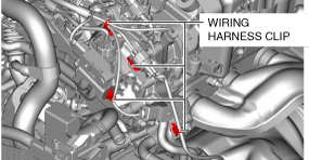
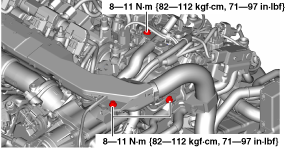
8.  Remove the bolts shown in the figure.

am3zzw00035913

9.  Disconnect the wiring harness clip shown in the figure.

am3zzw00035914

10.  Remove the wiring harness bracket.

am3zzw00035778

11.  Set the EGR cooler aside. (See EGR COOLER REMOVAL/INSTALLATION [SKYACTIV-X 2.0].)

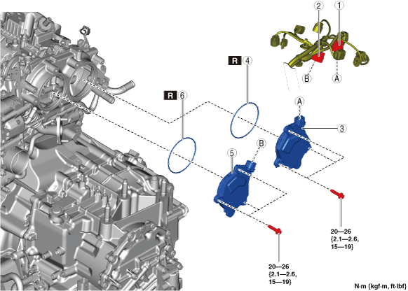
12.  Remove using the procedure shown in the figure.

13.  Install in the reverse order of removal.

am3zzw00034971

1
Exhaust electric variable valve timing motor/driver connector
2
Intake electric variable valve timing motor/driver connector
3
Exhaust electric variable valve timing motor/driver
4
O-ring
5
Intake electric variable valve timing motor/driver
6
O-ring


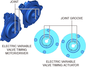
Electric Variable Valve Timing Motor/Driver Installation Note

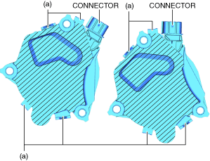
1.  Install the O-rings to the O-ring installation grooves in the engine rear cover (upper).

Caution
•  Be careful of the following to prevent damaging the electric variable valve timing motor/driver.
―  Do not apply force greater than 100 N to the shaded areas and connector areas in the figure.
ac30zw00004670
―  Do not deform locations (a) in the figure.
―  Do not handle the electric variable valve timing motor/driver by holding only the connector areas.
―  Do not touch the connector terminals.

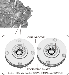
2.  Install the electric variable valve timing motor/driver using the following procedure.

Note
•  The eccentric shafts on the variable valve timing actuator side can be rotated to the left and right.
am3zzw00034973
•  When assembling the electric variable valve timing motor/driver, the position of the joint groove of the eccentric shaft does not affect the vehicle such as by causing damage to the vehicle or performance to decrease.
(1)  Before installation, rotate the joint part on the end of the electric valve timing motor so that it will align with the joint groove of the electric valve timing actuator.
am3zzw00034974
(2)  Connect the joint part on the end of the electric variable valve timing motor to the joint groove on the electric variable timing actuator side.
(3)  Seat the sealing surface.
(4)  Tighten the installation bolts of the electric variable valve timing motor/driver.