49 JP09 0A0
Injector remover

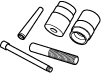
49 JP11 0A0
Injector seal installer set
FUEL INJECTOR REMOVAL/INSTALLATION [SKYACTIV-X 2.0]
id0114hf800600
Special Service Tool (SST)
|
49 JP09 0A0
Injector remover
|
|
49 JP11 0A0
Injector seal installer set
|
|
Replacement part
|
Fuel injector bracket
Quantity: 2
Location of use: Fuel injector
|
O-ring
Quantity: 4
Location of use: Fuel injector
|
Gas seal
Quantity: 8
Location of use: Fuel injector
|
Oil and chemical type
|
Engine oil
Type: Recommended oil
|
1. Perform the [Fuel Line Safety Procedure] referring to the [BEFORE SERVICE PRECAUTION]. (See BEFORE SERVICE PRECAUTION [SKYACTIV-X 2.0].)
2. Disconnect the negative battery terminal. (See NEGATIVE BATTERY TERMINAL DISCONNECTION/CONNECTION [(E)].)
3. Remove the engine cover. (See ENGINE COVER REMOVAL/INSTALLATION [SKYACTIV-X 2.0].)
4. Remove the following parts. (See SIDE WALL REMOVAL/INSTALLATION [SKYACTIV-X 2.0].)
5. Remove the seal cover. (See SEAL COVER REMOVAL/INSTALLATION [SKYACTIV-X 2.0].)
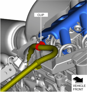
6. Remove the clip shown in the figure.
am3zzw00035656
|
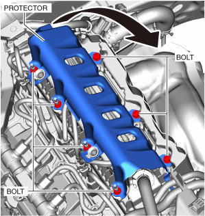
7. Remove the bolts and nuts and set the protector aside. (See SEAL COVER REMOVAL/INSTALLATION [SKYACTIV-X 2.0].)
am3zzw00035657
|
8. Remove the injection pipe (fuel injector side). (See INJECTION PIPE REMOVAL/INSTALLATION [SKYACTIV-X 2.0].)
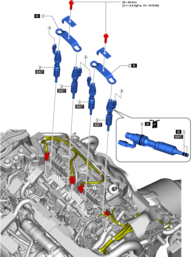
9. Remove using the procedure shown in the figure.
10. Install in the reverse order of removal.
11. If the fuel injector is replaced, perform the fuel injection amount learning. (See FUEL INJECTION AMOUNT LEARNING [SKYACTIV-X 2.0].)
ac30zw00004930
|
|
1
|
Fuel injector connector
|
|
2
|
Fuel injector bracket
|
|
3
|
Fuel injector
(See Fuel Injector Removal Note.)
|
|
4
|
O-ring
(See O-Ring Installation Note.)
|
|
5
|
Gas seal
(See Gas Seal Removal Note.)
(See Gas Seal Installation Note.)
|
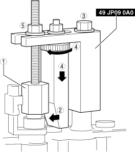
Fuel Injector Removal Note
1. Install the SST (49 JP09 0A0) in the order shown in the figure.
am30jw00000109
|
2. Tighten No.5 shown in the figure and remove the fuel injector.
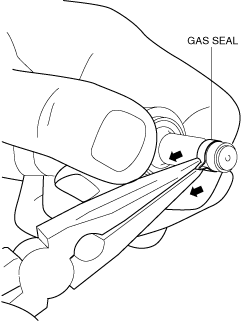
Gas Seal Removal Note
1. Stretch the gas seal as shown in the figure.
am3zzw00035659
|
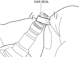
2. Remove the gas seal.
ac30zw00004931
|
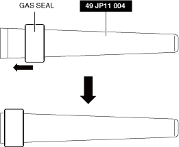
Gas Seal Installation Note
1. Insert the SST (49 JP11 004) into the gas seal and move it to the end.
ac30zw00004932
|
2. Install the SST (49 JP11 004) which the seal is installed to the end area of the fuel injector.
am3zzw00035661
|
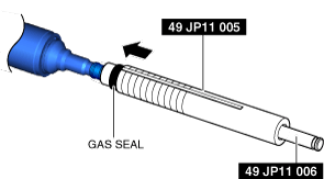
3. Press the gas seal to the fuel injector side using the SST 49 JP11 005 and 49 JP11 006.
ac30zw00004933
|
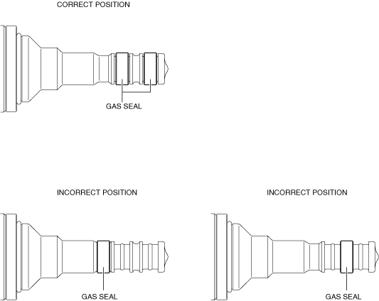
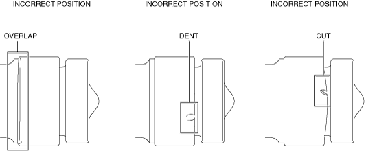
4. Verify that the gas seals are installed to the correct positions as shown in the figure.
ac30zw00004934
|
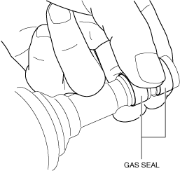
5. Lightly press the installed gas seals installed as shown in the figure, align them with the fuel injector grooves, and then smooth them evenly with fingers.
ac30zw00004935
|
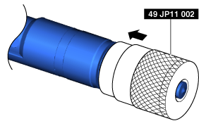
6. Slide the SST (49 JP11 002) to the end area of the fuel injector.
am30jw00000113
|
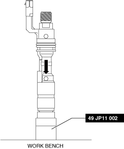
7. Put the fuel injector with the installed SST (49 JP11 002) on the work bench as shown in the figure and press in the fuel injector until it contacts the SST.
ac30zw00004936
|
8. Maintain the SST for approx. 3 min.
9. Verify that the gas seals are not damaged.
ac30zw00004937
|
10. Change from the SSTs (49 JP11 004, 49 JP11 002) used in Steps 1 and 6 to the SSTs (49 JP11 001, 49 JP11 003) and install the second gas seal using the same procedure as in Steps 1 to 9.
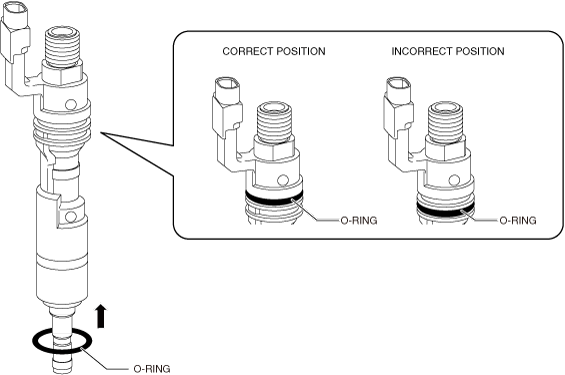
O-Ring Installation Note
1. Insert an O-ring from the end of the fuel injector as shown in the figure and install it to the correct position.
ac30zw00004938
|
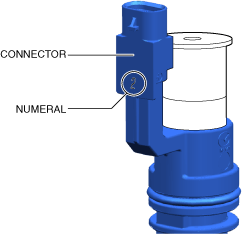
Fuel Injector Installation Note
Replacing with a new fuel injector
1. Verify that the numeral [2] is indicated on the connector area of the new fuel injector.
ac30zw00004939
|
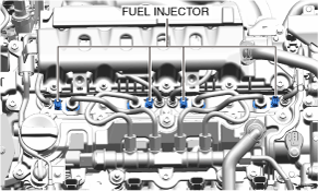
2. As shown in the figure, temporarily install the fuel injectors to the fuel injector installation holes being careful of the direction in which the fuel injectors are pointed.
ac30zw00004940
|
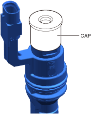
3. Press the top of the cap installed to the new fuel injector and press in the fuel injector until it is seated.
ac30zw00004941
|
4. Remove the cap.
5. Align the connection areas of the fuel injectors with the fuel injector bracket installation holes and assemble.
ac30zw00004942
|
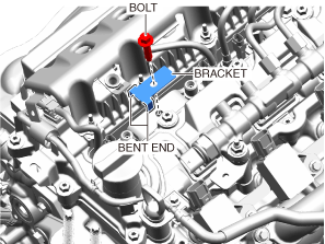
6. Install the bracket following procedure.
ac30zw00004943
|
Fuel injector is reused
ac30zw00004944
|
1. As shown in the figure, temporarily install the fuel injectors to the fuel injector installation holes being careful of the direction in which the fuel injectors are pointed.
ac30zw00004940
|
2. Align the connection areas of the fuel injectors with the fuel injector bracket installation holes and assemble.
ac30zw00004942
|
3. Install the bracket following procedure.
ac30zw00004943
|