 |
ac30zw00002211
FUEL TANK REMOVAL/INSTALLATION [SKYACTIV-D 1.8]
id0114q9801600
1. Level the vehicle.
2. Complete the “BEFORE SERVICE PRECAUTION”. (See BEFORE SERVICE PRECAUTION [SKYACTIV-D 1.8].)
3. Drain the fuel. (See FUEL DRAINING PROCEDURE [SKYACTIV-D 1.8].)
4. Remove the rear seat cushion. (See REAR SEAT CUSHION REMOVAL/INSTALLATION.)
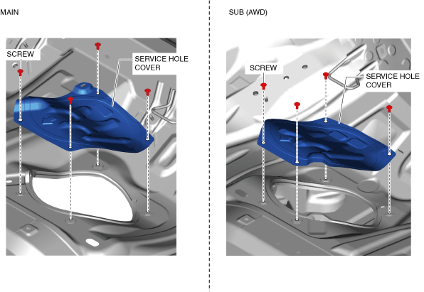
5. Remove the service hole cover.
ac30zw00002211
|
6. Disconnect the following parts:
7. Remove the floor under cover No.1 (LH). (See FLOOR UNDER COVER REMOVAL/INSTALLATION.)
8. Remove the floor under cover No.2. (See FLOOR UNDER COVER REMOVAL/INSTALLATION.)
9. Remove the ammonia slip catalyst component. (See EXHAUST SYSTEM REMOVAL/INSTALLATION [SKYACTIV-D 1.8].)
10. Remove the propeller shaft. (AWD) (See PROPELLER SHAFT REMOVAL/INSTALLATION [(E)].)
11. Remove the insulator (middle). (See EXHAUST SYSTEM REMOVAL/INSTALLATION [SKYACTIV-D 1.8].)
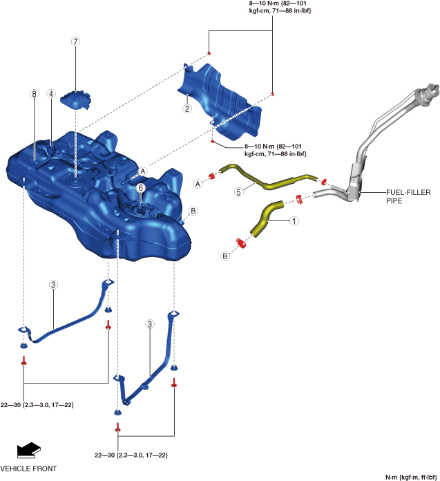
12. Remove in the order shown in the figure.
13. Install in the reverse order of removal.
14. Complete the “AFTER SERVICE PRECAUTION”. (See AFTER SERVICE PRECAUTION [SKYACTIV-D 1.8].)
2WD
ac30zw00002212
|
|
1
|
Joint hose
(See Joint Hose Installation Note.)
|
|
2
|
Fuel tank insulator
|
|
3
|
Fuel tank strap
|
|
4
|
Fuel tank
(See Fuel Tank Removal Note (2WD).)
|
|
5
|
Breather hose
|
|
6
|
Fuel gauge sender unit
|
|
7
|
Cover
|
|
8
|
Evaporative chamber
|
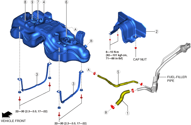
AWD
ac30zw00002213
|
|
1
|
Joint hose
(See Joint Hose Installation Note.)
|
|
2
|
Fuel tank insulator
|
|
3
|
Fuel tank strap
|
|
4
|
Fuel tank
(See Fuel Tank Removal Note (AWD).)
|
|
5
|
Breather hose
|
|
6
|
Fuel gauge sender unit (main)
|
|
7
|
Quick release connector
|
|
8
|
Evaporative chamber
|
|
9
|
Fuel gauge sender unit (sub)
|
Fuel Tank Removal Note (2WD)
1. Remove the following parts as a single unit:
2. Remove the fuel tank.
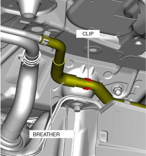
Fuel Tank Removal Note (AWD)
1. Disconnect the breather hose from the clip.
ac30zw00002214
|
2. Remove the following parts as a single unit:
3. Remove the fuel tank.
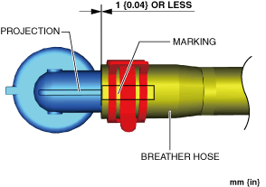
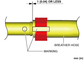
Breather Hose Installation Note (2WD)
1. Install the breather hose as shown in the figure.
Fuel tank side
am3zzw00021225
|
Joint pipe side
am3zzw00021191
|
Fuel Tank Installation Note (2WD)
1. Install the following parts as a single unit:
Fuel Tank Installation Note (AWD)
1. Install the following parts as a single unit:
2. Connect the breather hose to the clip.
ac30zw00002214
|
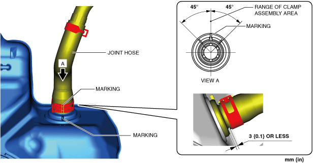
Joint Hose Installation Note
1. Align the joint hose marking with the pipe marking as shown in the figure and assemble.
Fuel tank side
am3zzw00022971
|
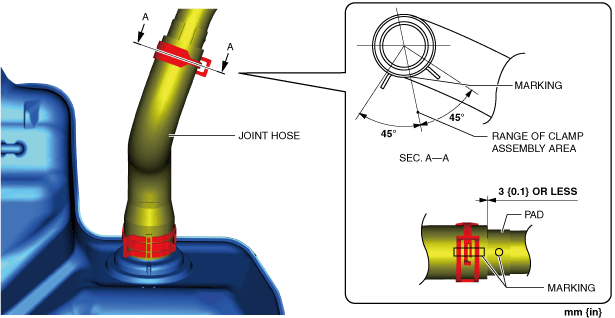
2. Align the joint hose marking with the fuel-filler pipe marking as shown in the figure and assemble.
Fuel-filler pipe side
am3zzw00029204
|