|
1
|
INSPECT BRAKE FLUID LEVEL
• Inspect the brake fluid level.
• Is the brake fluid level normal?
|
Yes
|
Go to the next step.
|
|
No
|
Add genuine brake fluid and go to the next step.
|
|
2
|
INSPECT BRAKE PIPE AND BRAKE HOSE FOR BRAKE FLUID LEAKAGE
• Perform the brake fluid leakage inspection for the brake pipe and brake hose.
• Is there brake fluid leakage?
|
Yes
|
Repair or replace the malfunctioning location and perform the repair completion verification.
|
|
No
|
Go to the next step.
|
|
3
|
INSPECT ELECTRONICALLY CONTROLLED BRAKE UNIT FOR BRAKE FLUID LEAKAGE
• Remove the brake pedal and inspect the electronically controlled brake unit for brake fluid leakage.
• Is there brake fluid leakage?
|
Yes
|
Repair or replace the malfunctioning location and perform the repair completion verification 2.
|
|
No
|
Go to the next step.
|
|
4
|
VERIFY IF AIR IS TRAPPED IN BRAKE LINE
• Select the following items from the initialization screen of the M-MDS.
-
1. “Toolbox”
2. “Work Support”
3. “BRAKES”
4. “Self-Diagnosing Brake Line”
• Perform the Self-Diagnosing Brake Line according to the directions on the screen.
• Is the result normal?
|
Yes
|
Go to the next step.
|
|
No
|
Bleed the air from the brake fluid according to the diagnostic result, and go to the repair completion verification.
|
|
5
|
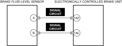
INSPECT BRAKE FLUID LEVEL SENSOR SIGNAL CIRCUITS FOR SHORT CIRCUIT
• Inspect the applicable circuits for short circuit.
• Is the circuit normal?
|
Yes
|
Go to the next step.
|
|
No
|
Repair or replace the malfunctioning location and perform the repair completion verification.
|
|
6
|
INSPECT BRAKE FLUID LEVEL SENSOR FOR MALFUNCTION
• Inspect the applicable part.
• Is the part normal?
|
Yes
|
Go to the next step.
|
|
No
|
Repair or replace the malfunctioning location and perform the repair completion verification.
|
|
Repair completion verification 1
|
VERIFY THAT VEHICLE IS REPAIRED
• Install/connect the part removed/disconnected during the troubleshooting procedure.
• Clear the DTC recorded in the memory.
• Perform the work of depressing the brake pedal for 3 s or more and then releasing it for 5 times or more with the ignition switched ON (engine off or on).
• Perform the DTC inspection for the electronically controlled brake unit.
• Is the same Pending DTC present?
|
Yes
|
Refer to the controller area network (CAN) malfunction diagnosis flow to inspect for a CAN communication error.
If the CAN communication is normal, perform the diagnosis from Step 1.
• If the malfunction recurs, replace the electronically controlled brake unit, then go to the next step.
|
|
No
|
Go to the next step.
|
|
Repair completion verification 2
|
VERIFY IF OTHER DTCs DISPLAYED
• Perform the DTC inspection.
• Are any DTCs displayed?
|
Yes
|
Repair the malfunctioning location according to the applicable DTC troubleshooting.
|
|
No
|
DTC troubleshooting completed.
|