1. : Mazda SST number
2. : Global SST number
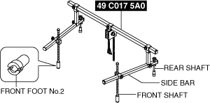
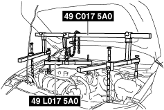
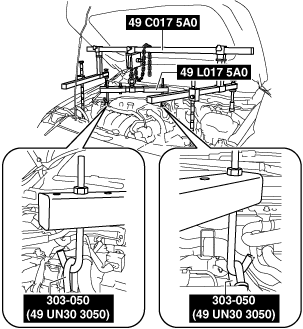
1: 49 C017 5A0
2: –
Engine support set
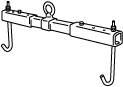
1: 49 UN30 3050
2: 303–050
Engine lifting bracket
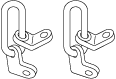
1: 49 L017 5A0
2: –
Support hanger
MANUAL TRANSAXLE REMOVAL/INSTALLATION [C66M-R]
id0515m8160000
Special Service Tool (SST)
|
1. : Mazda SST number
2. : Global SST number
|
|||||
|
1: 49 C017 5A0
2: –
Engine support set
|
|
1: 49 UN30 3050
2: 303–050
Engine lifting bracket
|
|
1: 49 L017 5A0
2: –
Support hanger
|
|
Removal
1. Disconnect the negative battery terminal .
2. Remove the plug hole plate.
3. Remove the tunnel cover.
4. Remove the front under cover No.2. (See FRONT UNDER COVER No.2 REMOVAL/INSTALLATION.)
5. Remove the front under cover No.1. (See FRONT UNDER COVER No.1 REMOVAL/INSTALLATION.)
6. Remove the front deflector. (See DEFLECTOR REMOVAL/INSTALLATION.)
7. Remove the front splash shield. (See SPLASH SHIELD REMOVAL/INSTALLATION.)
8. Drain the manual transaxle oil. (See MANUAL TRANSAXLE OIL REPLACEMENT [C66M-R].)
9. Drain the engine coolant.
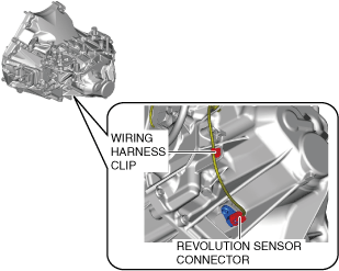
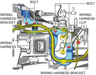
10. Disconnect the revolution sensor connector and wiring harness clip.
am3zzw00024644
|
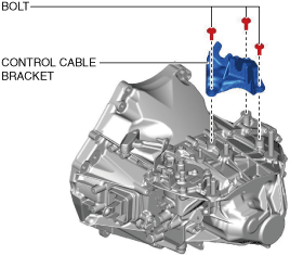
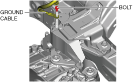
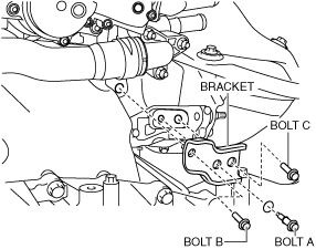
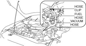
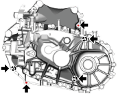
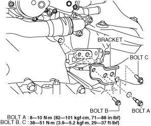
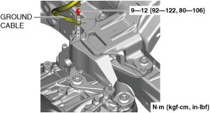
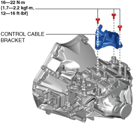
11. Disconnect or remove the following parts in the engine compartment.
am3zzw00021664
|
am3zzw00021665
|
ac30zw00004296
|
am3zzw00021666
|
12. Remove the joint cover.
13. Disconnect the intermediate shaft (lower side) from the steering gear and linkage.
14. Disconnect or remove the following parts related to the suspension and axle.
15. Remove the following parts from the underside of the vehicle.
am3zzw00021667
|
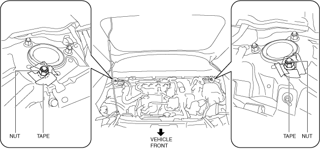
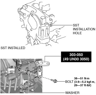
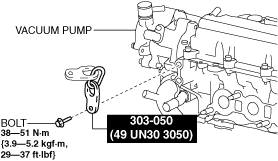
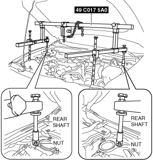
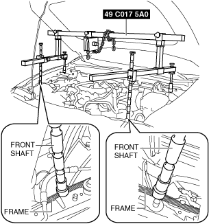
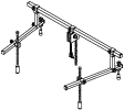
16. Install the SST using the following procedure.
am3uuw00008845
|
am3zzw00022325
|
ac30zw00003386
|
Engine front side
ac30zw00000603
|
Engine rear side
am3zzw00031863
|
am3zzw00022328
|
am3zzw00022329
|
am3zzw00022330
|
am3zzw00022331
|
am3zzw00022332
|
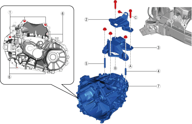
17. Remove in the order indicated in the table.
am3zzw00022737
|
|
1
|
Transaxle mounting bolt (upper side)
|
|
2
|
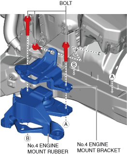
No.4 engine mount bracket
|
|
3
|
No.4 engine mount rubber
|
|
4
|
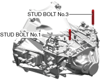
Stud bolt No.1
|
|
5
|
Stud bolt No.3
|
|
6
|
Transaxle mounting bolt (lower side)
|
|
7
|
Manual transaxle
|
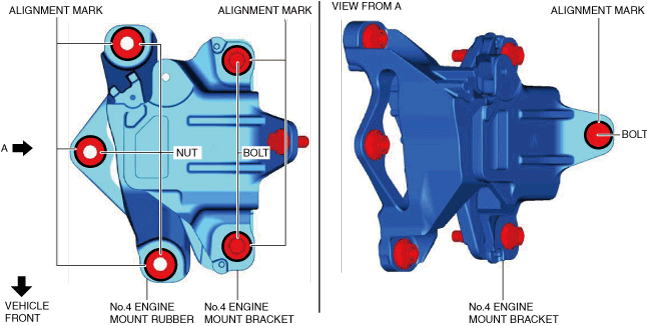
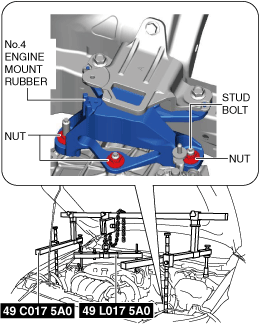
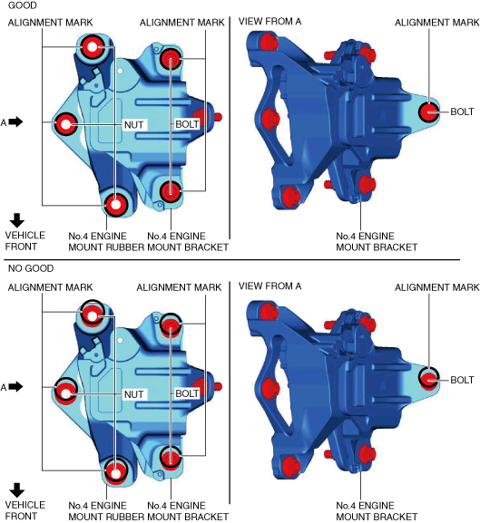
No.4 engine mount rubber and No.4 engine mount bracket removal note
1. Place alignment marks on the locations shown in the figure so that they can be assembled to the same positions as before removal.
am3zzw00021669
|
2. Remove the No.4 engine mount rubber and the No.4 engine mount bracket.
Transaxle mounting bolt removal note
1. Adjust the SST and lean the engine toward the manual transaxle.
am3zzw00022331
|
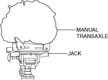
2. Support the manual transaxle on a jack.
ac5uuw00003118
|
3. Remove the transaxle mounting bolts (lower side).
am3zzw00027658
|
4. Remove the manual transaxle.
Installation
ac30zw00004727
|
1. Set the manual transaxle on a jack and lift into place.
ac5uuw00003118
|
2. Install the manual transaxle to the engine, and tighten the transaxle mounting bolts.
am3zzw00031864
|
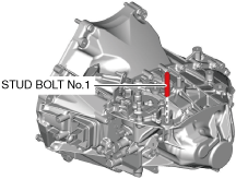
3. Install stud bolt No.1.
am3zzw00021670
|
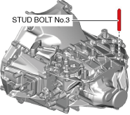
4. Install stud bolt No.3.
am3zzw00021671
|
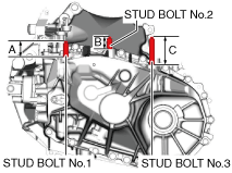
5. Measure the projection of the stud bolts.
am3zzw00021672
|
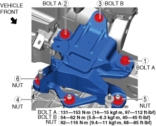
6. Install the No.4 engine mount bracket and the No.4 engine mount rubber, and temporarily tighten the bolts shown in the figure.
am3zzw00021673
|
7. Lift up the transaxle using the SSTs, pass the stud bolt through the No.4 engine mount rubber, and temporarily tighten the No.4 engine mount rubber installation nuts.
am3zzw00021674
|
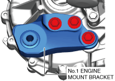
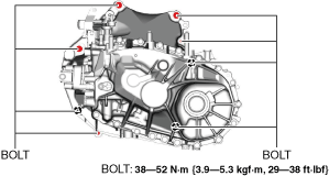
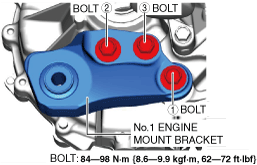
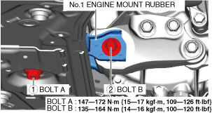
8. Install the No.1 engine mount bracket, and tighten the installation bolts in the order shown in the figure.
am3zzw00031865
|
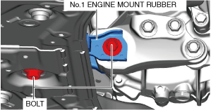
9. Install the front crossmember component and No.1 engine mount rubber as a single unit.
10. Temporarily tighten the No.1 engine mount rubber installation bolts.
am3zzw00021676
|
11. Align the nuts and bolts shown in the figure with the alignment marks.
am3zzw00021677
|
12. Tighten the No.4 engine mount rubber installation nuts and the No.4 engine mount bracket installation bolts in the order shown in the figure.
ac30zw00004728
|
13. Remove the SST (49 C017 5A0).
14. Tighten the No.1 engine mount rubber installation bolts in the order shown in the figure.
am3zzw00031867
|
15. Install the following parts to the underside of the vehicle.
16. Connect or Install the following parts related to the suspension and axle.
17. Connect the intermediate shaft (lower side) to the steering gear and linkage.
18. Install the joint cover.
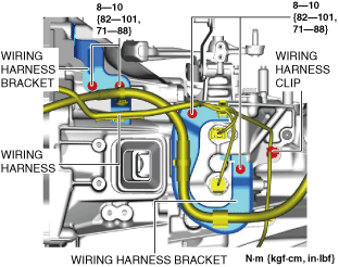
19. Connect or install the following parts in the engine compartment.
am3zzw00022330
|
ac30zw00003386
|
am3zzw00021680
|
am3zzw00031860
|
am3zzw00031868
|
am3zzw00021682
|
20. Install the front splash shield. (See SPLASH SHIELD REMOVAL/INSTALLATION.)
21. Install the front deflector. (See DEFLECTOR REMOVAL/INSTALLATION.)
22. Refill the engine coolant.
23. Connect the revolution sensor connector and wiring harness clip.
am3zzw00024644
|
24. Add the specified amount of specified manual transaxle oil. (See MANUAL TRANSAXLE OIL REPLACEMENT [C66M-R].)
25. Install the tunnel cover.
26. Install the front under cover No.1. (See FRONT UNDER COVER No.1 REMOVAL/INSTALLATION.)
27. Install the front under cover No.2. (See FRONT UNDER COVER No.2 REMOVAL/INSTALLATION.)
28. Connect the negative battery terminal.
29. Install the plug hole plate.
30. If the manual transaxle is overhauled, perform the “INSPECTION AFTER MANUAL TRANSAXLE OVERHAUL”. (See INSPECTION AFTER MANUAL TRANSAXLE OVERHAUL [C66M-R].)