1. Disconnect the negative battery cable.
2. Drain the engine coolant, engine oil, and transaxle oil.
3. Remove the radiator. (See RADIATOR REMOVAL/INSTALLATION [MZR-CD (RF Turbo)].)
4. Remove the engine cover. (See TIMING BELT REMOVAL/INSTALLATION [MZR-CD (RF Turbo)].)
5. Remove the air cleaner and air hose. (See INTAKE-AIR SYSTEM REMOVAL/INSTALLATION [MZR-CD (RF Turbo)].)
6. Disconnect the fuel hose. (See BEFORE REPAIR PROCEDURE [MZR-CD (RF Turbo)].)
7. Remove the front pipe. (See EXHAUST SYSTEM REMOVAL/INSTALLATION [MZR-CD (RF Turbo)].)
8. Remove the battery and tray. (See BATTERY REMOVAL/INSTALLATION [MZR-CD (RF Turbo)].)
9. Remove the shift cable, select cable and clutch release cylinder related to the transaxle. (See MANUAL TRANSAXLE REMOVAL/INSTALLATION [A26M-R].)
10. Remove the clutch release cylinder. (See CLUTCH RELEASE CYLINDER REMOVAL/INSTALLATION.)
11. Remove the vacuum hose and the heater hose.
12. Disconnect the P/S oil pump pressure pipe and P/S oil pump relief hose from the P/S oil pump side. (See POWER STEERING OIL PUMP REMOVAL/INSTALLATION [MZR-CD (RF Turbo)].)
13. Remove the A/C compressor with the pipe still connected. Position the A/C compressor so that it is out of the way. Use wire or rope to secure it. (See A/C COMPRESSOR REMOVAL/INSTALLATION [MZR-CD (RF Turbo)].)
14. Remove the joint shaft. (See JOINT SHAFT REMOVAL/INSTALLATION [L8, LF, L3, MZR-CD (RF Turbo)].)
15. Remove the front drive shaft (LH) from the transaxle. (See FRONT DRIVE SHAFT REMOVAL/INSTALLATION [L8, LF, L3, MZR-CD (RF Turbo)].)
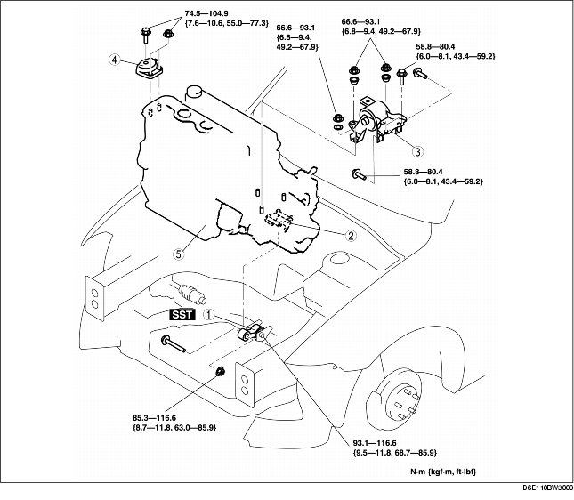
16. Remove in the order indicated in the table.
17. Install in the reverse order of removal.
18. Fill the engine coolant, engine oil, and transaxle oil.
19. Bleed the air from the fuel line. (See AFTER REPAIR PROCEDURE [MZR-CD (RF Turbo)].)
20. Start the engine and:
21. Perform a road test.
22. Reinspect the engine oil, engine coolant, transaxle oil, and P/S fluid levels.
|
1
|
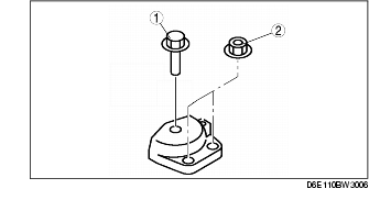
No.1 Engine mount rubber
|
|
2
|
No.1 Engine mount bracket
|
|
3
|
No.4 Engine mount bracket and No.4 Engine mount rubber
|
|
4
|
No.3 Engine joint bracket
|
|
5
|
Engine, transaxle
|
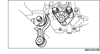
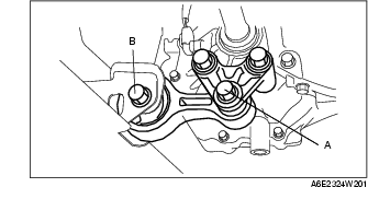
1. Remove through-bolt A on the No.1 engine mount bracket side.
2. Loosen through-bolt B on the front crossmember side until approximately three pitches are showing.
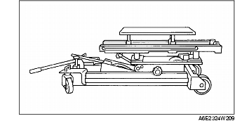
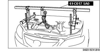
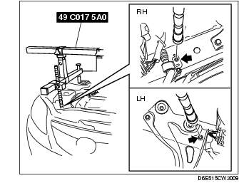
1. Install the SST using the following procedure.


2. Support the engine using the SST.
3. Secure the engine and the transaxle using an engine jack and attachment as shown.
4. Remove the SST.
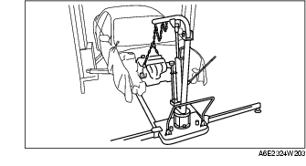
5. Secure the engine and the transaxle using a hoist.
6. Remove the No.4 engine mount bracket and engine mount rubber together as a unit.
1. Secure the engine and the transaxle using an engine jack and attachment as shown.
2. Install the SST using the following procedure.
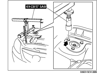
3. Support the engine using the SST.
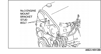
4. Tighten the No.3 engine mount bracket stud bolt.
5. Tighten the No.3 engine joint bracket bolt and nut in the order as shown.
Tightening torque
74.5-104.9 N·m {7.6-10.6 kgf·m, 55.0-73.3 ft·lbf}
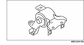
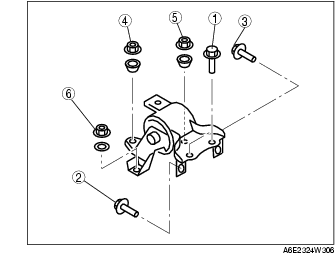
1. Tighten the No.4 engine mount bracket and No.4 engine mount rubber bolt and nut in the order as shown.
|
Bolt or nut No.
|
Tightening torque
(N·m {kgf·m, ft·lbf})
|
|---|---|
|
1, 2, 3
|
58.8-80.4 {6.0-8.1, 43.4-59.2} |
|
4, 5, 6
|
66.6-93.1 {6.8-9.4, 49.2-67.9} |
2. Secure the engine and the transaxle using an engine jack and attachment as shown.
3. Remove the hoist and secure the engine and transaxle using SST.
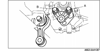
1. Tighten No.1 engine mount bracket bolt A.
2. Tighten No.1 engine mount bracket bolt B.
1. Tighten through-bolt A on the No.1 engine mount bracket.
2. Tighten through-bolt B on the front crossmember side.