Home

Mazdamanuals.com

 FRONT CROSSMEMBER REMOVAL/INSTALLATION

FRONT CROSSMEMBER REMOVAL/INSTALLATION


id021300801000

1. Remove the under cover.

2. Remove the splash shield.

3. Remove the front auto leveling sensor.(See FRONT AUTO LEVELING SENSOR REMOVAL/INSTALLATION.)

4. Remove the transverse member.(See TRANSVERSE MEMBER REMOVAL/INSTALLATION.)

5. Remove the steering gear and linkage, and pipe assembly installation bolts from the front crossmember, then suspend the steering gear and linkage with a cable.
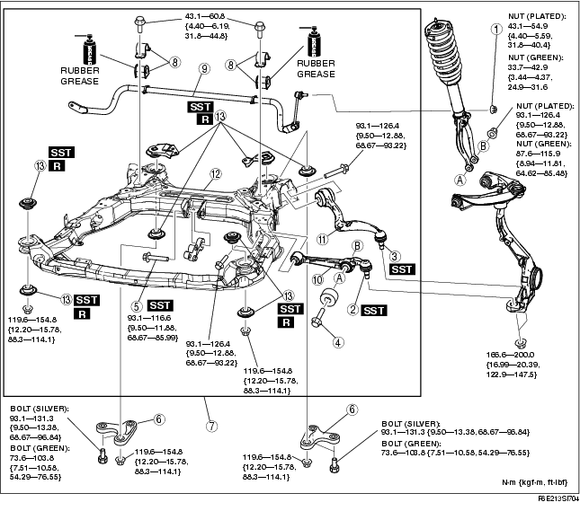
Tightening torque
• Steering gear and linkage: 74.4-104.8 N·m {7.857-10.68 kgf·m, 54.88-77.29 ft·lbf}
• Pipe assembly: 7.8-10.8 N·m {79.6-110.0 kgf·cm, 69.1-95.5 in·lbf}

6. Remove in the order indicated in the table.

7. Install in the reverse order of removal.

8. Adjust the headlight zeroset.(See HEADLIGHT ZEROSET.)

9. Inspect the front wheel alignment.(See FRONT WHEEL ALIGNMENT.)

.

1
Nut (stabilizer control link)
2
Front lower arm (front) ball joint
3
Front lower arm (rear) ball joint
4
Bolt (front shock absorber lower side)
5
No.1 engine mount center bolt
6
Crossmember bracket
7
Crossmember component
8
Stabilizer bracket and bushing
9
Front Stabilizer
10
Front lower arm (front)
11
Front lower arm (rear)
12
Front crossmember
13
Front crossmember bushing

Crossmember Bracket Removal Note

Warning
• Removing the crossmember is dangerous. The crossmember component could fall and cause serious injury or death. Verify that the jack securely supports the crossmember component before removing the crossmember bracket.

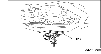
1. Support the crossmember component with a jack and remove the nuts.

2. Remove the crossmember bracket.

Front Crossmember Bushing Removal Note

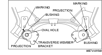
1. Mark the crossmember as shown in the figure (rear upper side only).

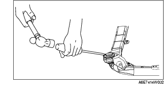
2. Remove the bushings using screw driver (-), being care not to damage the front crossmember.

Front Crossmember Bushing Installation Note

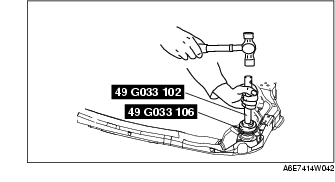
1. Set the bushings as shown in the figure.

2. Install the bushing onto the crossmember using the SSTs.