STEERING GEAR AND LINKAGE REMOVAL/INSTALLATION [L3 (4WD), L3 Turbo]
STEERING GEAR AND LINKAGE REMOVAL/INSTALLATION [L3 (4WD), L3 Turbo]
id0614008009a7
-
Caution
-
• Performing the following procedures without first removing the ABS wheel-speed sensor may possibly cause an open circuit in the harness if it is pulled by mistake. Before performing the following procedures, remove the ABS wheel-speed sensor (axle side) and fix it to an appropriate place where the sensor will not be pulled by mistake while servicing the vehicle.
1. Remove the joint cover.
2. Remove the ABS wheel-speed sensor. (See FRONT ABS WHEEL-SPEED SENSOR REMOVAL/INSTALLATION.)
3. Remove the under cover and splash shield.
4. Remove the front auto leveling sensor. (See FRONT AUTO LEVELING SENSOR REMOVAL/INSTALLATION.)
5. Separate the stabilizer control link (shock absorber side). (SeeFRONT STABILIZER REMOVAL/INSTALLATION.)
6. Separate the front lower arm (front and rear) ball joint. (See FRONT LOWER ARM (FRONT) REMOVAL/INSTALLATION.)
7. Remove the shock absorber bolt (lower side). (SeeFRONT SHOCK ABSORBER AND SPRING REMOVAL/INSTALLATION.)
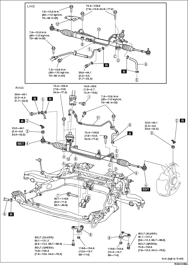
8. Remove in the order indicated in the table.
9. Install in the reverse order of removal.
10. After installation, inspect the front wheel alignment. (See FRONT WHEEL ALIGNMENT.)
11. Adjust the headlight zeroset. (See HEADLIGHT ZEROSET.)
.
|
1
|
Bolt (intermediate shaft)
|
|
2
|
Cotter pin
|
|
3
|
Nut (tie-rod end ball joint)
|
|
4
|
Tie-rod end ball joint
|
|
5
|
Pressure pipe
|
|
6
|
Return hose
|
|
7
|
No.1 engine mount center bolt
|
|
8
|
Crossmember bracket
|
|
9
|
Crossmember component, steering gear and linkage
|
|
10
|
Steering gear and linkage
|
|
11
|
Return pipe
|
|
12
|
Insulator (18 inch wheel)
|
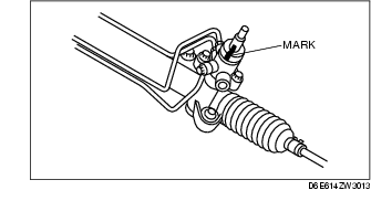
Bolt (Intermediate Shaft) Removal Note
1. Mark the pinion shaft and gear housing for proper installation.
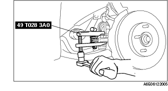
Tie-rod End Ball Joint Removal Note
1. Remove the tie rod-nut.
2. Separate the tie-rod end from the steering knuckle using the SSTs.
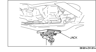
Crossmember Bracket Removal Note
-
Warning
-
• Removing the crossmember is dangerous. The crossmember component could fall and cause serious injury or death. Verify that the jack securely supports the crossmember component before removing the crossmember bracket.
1. Support the crossmember component with a jack and remove the nuts.
2. Remove the crossmember bracket.
Crossmember Component, Steering Gear And Linkage Removal Note
-
Warning
-
• Removing the crossmember is dangerous. The crossmember component could fall and cause serious injury or death. Verify that the jack securely supports the crossmember component before removing the crossmember bracket.
1. Remove the crossmember component, steering gear and linkage.
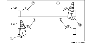
Steering Gear And Linkage Installation Note
1. Loosely tighten bolts.
2. Tighten the mounting bracket bolts to the specified torque in the order shown.
Tightening torque
-
74.4-104.8 N·m {7.6-10.6 kgf·m, 55-77 ft·lbf}
Bolt (Intermediate Shaft) Installation Note
1. Align the marks and install the intermediate shaft and bolt.