1. Remove the joint cover.
2. Remove the ABS wheel-speed sensor. (See FRONT ABS WHEEL-SPEED SENSOR REMOVAL/INSTALLATION.)
3. Remove the under cover and splash shield.
4. Remove the front auto leveling sensor. (See FRONT AUTO LEVELING SENSOR REMOVAL/INSTALLATION.)
5. Separate the stabilizer control link (shock absorber side). (SeeFRONT STABILIZER REMOVAL/INSTALLATION.)
6. Separate the front lower arm (front and rear) ball joint.FRONT LOWER ARM (FRONT) REMOVAL/INSTALLATION.)
7. Remove the shock absorber bolt (lower side). (SeeFRONT SHOCK ABSORBER AND SPRING REMOVAL/INSTALLATION.)
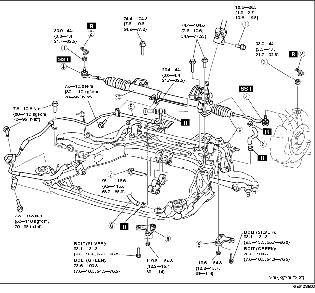
8. Remove in the order indicated in the table.
9. Install in the reverse order of removal.
10. After installation, inspect the front wheel alignment. (See FRONT WHEEL ALIGNMENT.)
11. Adjust the headlight zeroset. (See HEADLIGHT ZEROSET.)
.
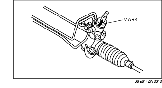
1. Mark the pinion shaft and gear housing for proper installation.
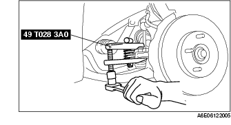
1. Remove the tie rod-nut.
2. Separate the tie-rod end from the steering knuckle using the SSTs.
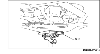
1. Support the crossmember component with a jack and remove the nuts.
2. Remove the crossmember bracket.
1. Remove the crossmember component, steering gear and linkage.
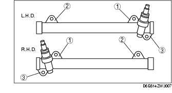
1. Loosely tighten bolts.
2. Tighten the mounting bracket bolts to the specified torque in the order shown.
Tightening torque
1. Align the marks and install the intermediate shaft and bolt.
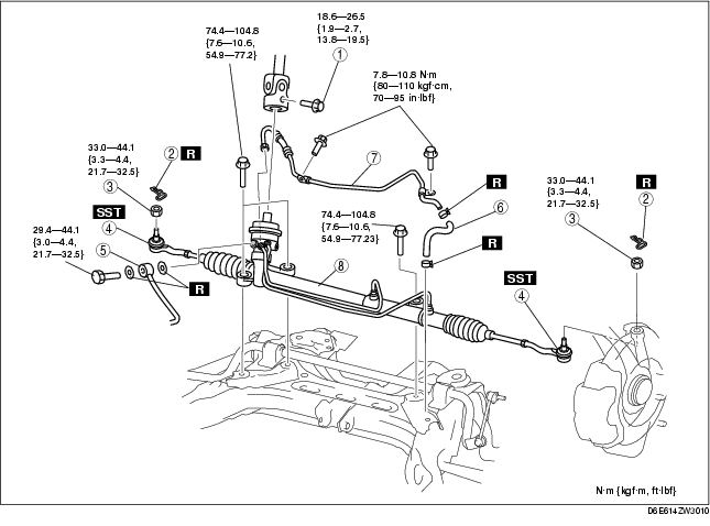
1. Remove in the order indicated in the table.
2. Install in the reverse order of removal.
3. After installation, inspect the front wheel alignment. (See FRONT WHEEL ALIGNMENT.)
.
|
1
|
Bolt (intermediate shaft)
|
|
2
|
Cotter pin
|
|
3
|
Nut
|
|
4
|
Tie-rod end ball joint
|
|
5
|
Pressure pipe
|
|
6
|
Return hose
|
|
7
|
Return pipe
|
|
8
|
Steering gear and linkage
|