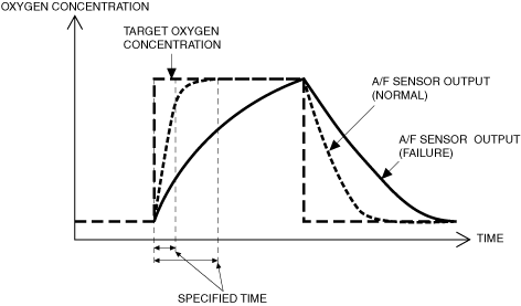
If the response speed of the signal input from the A/F sensor is slow while switching repeatedly between rich and lean, the PCM determines an A/F sensor malfunction and stores a DTC.
ac5uuw00009738
|
DTC P0133:00 [PCM (SKYACTIV-D)]
id0102t5702400
Details On DTCs
|
Description |
A/F sensor circuit slow response |
|
|---|---|---|
|
Detection condition
|
Determination conditions
|
• The response speed of the A/F sensor input signal is slow.
|
|
Preconditions
|
• A/F sensor is activated
• Engine coolant temperature: 50 °C {122 °F} or more
• Ambient air temperature: -10 °C {14 °F}
• Barometric pressure: 72 kPa {0.73 kgf/cm2, 10.4 psi} or more
• diesel particulate filter regeneration control is not operating
• DENOx control is not operating
• DESOx control is not operating
• Fuel injection control: except during fuel cut
• Amount of change in oxygen concentration in target exhaust gas: ±4% or more
• Vehicle speed: more than 0 km/h {0 rpm}
• The following DTCs are not detected
|
|
|
Drive cycle
|
• 1
|
|
|
Self test type
|
• CMDTC self test
|
|
|
Sensor used
|
• A/F sensor
|
|
|
Fail-safe
|
• PCM restricts engine torque./Limits the maximum engine speed.
• Inhibits the DENOx/DESOx control.
• Inhibits the diesel particulate filter regeneration control.
• Inhibits the EGR control.
|
|
|
Vehicle status when dtcs are output
|
• Illuminates check engine light.
|
|
|
Possible cause
|
• A/F sensor signal malfunction
• A/F sensor deterioration
• A/F sensor heater malfunction
• LP-EGR control valve malfunction
• HP-EGR control valve malfunction
• Exhaust shutter valve malfunction
• PCM malfunction
|
|
System Wiring Diagram
Function Explanation (DTC Detection Outline)
ac5uuw00009738
|
Repeatability Verification Procedure
1. Start the engine and warm up for 12 min or more with the engine coolant temperature at 60 °C {140 °F} or more.
2. Perform the following acceleration/deceleration driving 10 times repeatedly.
PID Item/Simulation Item Used In Diagnosis
PID/DATA monitor item table
|
Item (definition) |
Reference |
|---|---|
|
A/F_SEN_HEAT
|
|
|
A/F_SEN_CUR
|
|
|
A/F_SEN_OUT_VOLT
|
Function Inspection Using M-MDS
|
Step |
Inspection |
Results |
Action |
|---|---|---|---|
|
1
|
PURPOSE: VERIFY RELATED REPAIR INFORMATION OR SERVICE INFORMATION AVAILABILITY
• Verify related Service Bulletins, on-line repair information, or Service Information availability.
• Is any related Information available?
|
Yes
|
Perform repair or diagnosis according to the available information.
• If the vehicle is not repaired, go to the next step.
|
|
No
|
Go to the next step.
|
||
|
2
|
PURPOSE: IDENTIFY TRIGGER DTC FOR FREEZE FRAME DATA
• Is the DTC P0133:00 on FREEZE FRAME DATA?
|
Yes
|
Go to the next step.
|
|
No
|
Go to the troubleshooting procedure for DTC on FREEZE FRAME DATA.
(See DTC TABLE [PCM (SKYACTIV-D)].)
|
||
|
3
|
PURPOSE: RECORD VEHICLE STATUS WHEN DTC WAS DETECTED TO UTILIZE WITH REPEATABILITY VERIFICATION
• Record the freeze frame data/snapshot data.
|
—
|
Go to the next step.
|
|
4
|
PURPOSE: VERIFY IF DIAGNOSTIC RESULT IS AFFECTED BY DTC OCCURRING FROM A/F SENSOR UNIT
• Switch the ignition off, then ON (engine off).
• Perform the Pending Trouble Code Access Procedure and DTC Reading Procedure.
(See DTC INSPECTION.)
• Is the PENDING CODE/DTC P0134:00 also present?
|
Yes
|
Go to the applicable DTC inspection.
Go to the next step.
|
|
No
|
Go to the next step.
|
||
|
5
|
PURPOSE: VERIFY A/F SENSOR
• Start the engine and idle it.
• Access the A/F_SEN_CUR and A/F_SEN_OUT_VOLT PID using the M-MDS.
(See PID/DATA MONITOR INSPECTION.)
• Is the A/F_SEN_CUR and A/F_SEN_OUT_VOLT PID value normal?
|
Yes
|
Go to the next step.
|
|
No
|
Go to Troubleshooting Diagnostic Procedure to perform the procedure from step 1.
|
||
|
6
|
PURPOSE: VERIFY A/F SENSOR HEATER
• Start the engine and idle it.
• Access the A/F_SEN_HEAT PID using the M-MDS.
(See PID/DATA MONITOR INSPECTION.)
• Is the A/F_SEN_HEAT PID value normal?
|
Yes
|
Go to the next step.
|
|
No
|
Go to Troubleshooting Diagnostic Procedure to perform the procedure from step 5.
|
||
|
7
|
PURPOSE: VERIFY DTC
• Switch the ignition off, then ON (engine off).
• Retrieve the PCM DTCs using the M-MDS.
(See DTC INSPECTION.)
• Are any DTCs present?
|
Yes
|
Go to the applicable DTC inspection.
(See DTC TABLE [PCM (SKYACTIV-D)].)
Go to Troubleshooting Diagnostic Procedure to perform the procedure from step 1.
|
|
No
|
Go to Troubleshooting Diagnostic Procedure to perform the procedure from step 1.
|
Troubleshooting Diagnostic Procedure
|
Step |
Inspection |
Results |
Action |
|---|---|---|---|
|
1
|
PURPOSE: INSPECT A/F SENSOR CONNECTOR FOR MALFUNCTION
• Inspect the applicable connector and terminal.
(See CONNECTOR INSPECTION.)
• Are the connector and terminal normal?
|
Yes
|
Go to the next step.
|
|
No
|
Repair or replace the malfunctioning location and perform the repair completion verification.
|
||
|
2
|
PURPOSE: INSPECT INSTALLATION OF A/F SENSOR
• Inspect installation of A/F sensor.
• Is the A/F sensor installed securely?
|
Yes
|
Go to the next step.
|
|
No
|
Repair or replace the malfunctioning location and perform the repair completion verification.
|
||
|
3
|
PURPOSE: VERIFY IF MALFUNCTION RELATED TO EMISSION SYSTEM AFFECTS A/F SENSOR SIGNAL
• Inspect for exhaust gas leakage from the exhaust system. (between turbocharger and diesel particulate filter)
• Is there any malfunction?
|
Yes
|
Repair or replace the malfunctioning location and perform the repair completion verification.
|
|
No
|
Go to the next step.
|
||
|
4
|
PURPOSE: DETERMINE INTEGRITY OF A/F SENSOR
• Reconnect all disconnected connectors.
• Inspect the A/F sensor.
• Is there any malfunction?
|
Yes
|
Repair or replace the malfunctioning location and perform the repair completion verification.
|
|
No
|
Go to the next step.
|
||
|
5
|
PURPOSE: DETERMINE INTEGRITY OF A/F SENSOR HEATER
• Inspect the A/F sensor heater.
• Is there any malfunction?
|
Yes
|
Repair or replace the malfunctioning location and perform the repair completion verification.
|
|
No
|
Go to the next step.
|
||
|
6
|
PURPOSE: INSPECT EXHAUST SHUTTER VALVE FOR MALFUNCTION
• Inspect the applicable part.
• Is the part normal?
|
Yes
|
Go to the next step.
|
|
No
|
Repair or replace the malfunctioning location and perform the repair completion verification.
|
||
|
7
|
PURPOSE: INSPECT HP-EGR CONTROL VALVE FOR MALFUNCTION
• Inspect the applicable part.
• Is the part normal?
|
Yes
|
Go to the next step.
|
|
No
|
Repair or replace the malfunctioning location and perform the repair completion verification.
|
||
|
8
|
PURPOSE: INSPECT LP-EGR CONTROL VALVE FOR MALFUNCTION
• Inspect the applicable part.
• Is the part normal?
|
Yes
|
Go to the next step.
|
|
No
|
Repair or replace the malfunctioning location and perform the repair completion verification.
|
||
|
Repair completion verification 1
|
PURPOSE: VERIFY THAT VEHICLE IS REPAIRED
• Install/connect the part removed/disconnected during the troubleshooting procedure.
• Clear the DTC recorded in the memory.
(See CLEARING DTC.)
• Replicate the vehicle conditions at the time the DTC was detected using the following procedure.
• Perform the DTC inspection for the PCM.
(See DTC INSPECTION.)
• Is the same Pending DTC present?
|
Yes
|
Refer to the controller area network (CAN) malfunction diagnosis flow to inspect for a CAN communication error.
If the CAN communication is normal, perform the diagnosis from Step 1.
• If the malfunction recurs, replace the PCM, then go to the next step.
|
|
No
|
Go to the next step.
|
||
|
Repair completion verification 2
|
PURPOSE: VERIFY IF OTHER DTCs DISPLAYED
• Perform the DTC inspection.
(See DTC INSPECTION.)
• Are any other DTCs displayed?
|
Yes
|
Repair the malfunctioning location according to the applicable DTC troubleshooting.
|
|
No
|
DTC troubleshooting completed.
|