Home

Mazdamanuals.com

DTC P039E:00, P03A8:00, P03B2:00 OR P03BC:00 [PCM (SKYACTIV-X)]

DTC P039E:00, P03A8:00, P03B2:00 OR P03BC:00 [PCM (SKYACTIV-X)]


 id0102u9202800

Note
•  To determine the malfunctioning part, proceed with the diagnostics from "Function Inspection Using M-MDS".

Details On DTCs

Description

•  P039E:00: Cylinder pressure sensor No.1: Abnormal combustion
•  P03A8:00: Cylinder pressure sensor No.2: Abnormal combustion
•  P03B2:00: Cylinder pressure sensor No.3: Abnormal combustion
•  P03BC:00: Cylinder pressure sensor No.4: Abnormal combustion
Detection condition
Determination conditions
•  If any of the following conditions is met for a continuous specified period.
―  PCM determines that detected value for combustion status is unreliable
―  Signal voltage input from cylinder pressure sensor to PCM is abnormal
Preconditions
•  There is no misfire
•  Fuel-cut control not implemented
•  Vehicle is being driven within control range that allows detection of this DTC
•  The following DTCs are not detected:
―  Cylinder pressure sensor: P0396:00, P0397:00, P0398:00, P03A0:00, P03A1:00, P03A2:00, P03AA:00, P03AB:00, P03AC:00, P03B4:00, P03B5:00 or P03B6:00
―  CMP sensor: P0335:00
―  CKP sensor: P0340:00 or P0365:00
Drive cycle
•  1
Self test type
•  CMDTC self test, KOER self test
Sensor used
•  Cylinder pressure sensor No.1
•  Cylinder pressure sensor No.2
•  Cylinder pressure sensor No.3
•  Cylinder pressure sensor No.4
•  MAP sensor
•  CKP sensor
•  CMP sensor
Fail-safe function
•  Inhibits the EGR control.
•  Inhibits the SPCCI control.
•  Stops the combustion control feedback.
•  Retards the ignition timing.
Vehicle status when DTCs are output
•  Not applicable
Possible cause
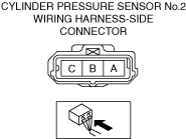
•  Cylinder pressure sensor connectors or terminals malfunction
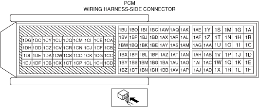
•  PCM connector or terminals malfunction
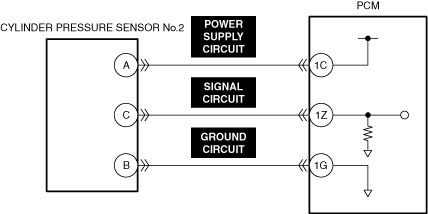
•  Short to ground in any of the following cylinder pressure sensor circuits.
―  Power supply circuit
―  Signal circuit
•  Short to power supply in cylinder pressure sensor signal circuit
•  Short circuit between any of the following cylinder pressure sensor circuits.
―  Power supply circuit
―  Signal circuit
―  Ground circuit
•  Open circuit in any of the following cylinder pressure sensor circuits.
―  Power supply circuit
―  Signal circuit
―  Ground circuit
•  Cylinder pressure sensor malfunction
•  Insufficient engine compression
•  Incorrect fuel injection timing
•  Fuel injector malfunction
•  Poor sealing of coolant passage (leakage of engine coolant into combustion chamber)
•  PCM malfunction


Function Explanation (DTC Detection Outline)

•  The PCM detects the combustion status based on the cylinder pressure sensor signal.
If a problem such as a poorly insulated cylinder pressure sensor, a malfunctioning sensor, or an abnormal signal voltage occurs, the PCM cannot determine the combustion status correctly, causing deteriorated combustion controllability.
The PCM determines the reliability of the signal based on the cylinder pressure sensor signal voltage value, and if the signal is unreliable for a continuous specified period, the PCM stores a DTC.

Repeatability Verification Procedure

1.  Start the engine.
2.  Race the engine at an engine speed of 3,000 rpm for 15 s.

PID Item/Simulation Item Used In Diagnosis

PID/DATA monitor item table

PIDs

Reference

MAX_CYL_PRES_#1
MAX_CYL_PRES_#2
MAX_CYL_PRES_#3
MAX_CYL_PRES_#4


Function Inspection Using M-MDS

Step

Inspection

Results

Action

1
PURPOSE: VERIFY RELATED REPAIR INFORMATION OR SERVICE INFORMATION AVAILABILITY
•  Verify related Service Bulletins, on-line repair information, or Service Information availability.
•  Is any related Information available?
Yes
Perform repair or diagnosis according to the available information.
•  If the vehicle is not repaired, go to the next step.
No
Go to the next step.
2
PURPOSE: RECORD VEHICLE STATUS WHEN DTC WAS DETECTED TO UTILIZE WITH REPEATABILITY VERIFICATION
•  Record the freeze frame data/snapshot data.
Note
•  Recording can be facilitated using the screen capture function of the PC.
Go to the next step.
3
PURPOSE: VERIFY CONNECTOR CONNECTIONS
•  Start the engine.
•  Access the following PIDs using the M-MDS:
―  MAX_CYL_PRES_#1
―  MAX_CYL_PRES_#2
―  MAX_CYL_PRES_#3
―  MAX_CYL_PRES_#4
•  Does the PID value fluctuate when the following connectors are shaken?
―  Cylinder pressure sensor No.1
―  Cylinder pressure sensor No.2
―  Cylinder pressure sensor No.3
―  Cylinder pressure sensor No.4
―  PCM
Yes
Repair or replace the applicable wiring harness or connector parts.
Go to Troubleshooting Diagnostic Procedure to perform the repair completion verification.
No
Go to Troubleshooting Diagnostic Procedure to perform the procedure from Step 1.
4
PURPOSE: INSPECT FOR OTHER RELATED DTCs
•  Perform the DTC inspection for the PCM.
•  Are any other DTCs displayed?
Yes
Repair the malfunctioning location according to the applicable DTC troubleshooting.
Go to Troubleshooting Diagnostic Procedure to perform the repair completion verification.
No
Go to Troubleshooting Diagnostic Procedure to perform the procedure from Step 1.


Troubleshooting Diagnostic Procedure

Intention of troubleshooting procedure
•  Step 1
―  Verify other related DTCs.
•  Step 2—8
―  Perform a unit inspection of the cylinder pressure sensor.
•  Step 9
―  Perform a unit inspection of the fuel injector.
•  Step 10
―  Inspect the engine compression pressure.
•  Step 11
―  Inspect for engine coolant leakage from the engine.
•  Repair completion verification
―  Verify that the primary malfunction is resolved and there are no other malfunctions.

Step

Inspection

Results

Action

1
PURPOSE: INSPECT FOR OTHER RELATED DTCs
•  Perform the DTC inspection for the PCM.
•  Are any of the following DTCs displayed?
―  P00300:00
―  P00301:00
―  P00302:00
―  P00303:00
―  P00304:00
Yes
Repair the malfunctioning location according to the applicable DTC troubleshooting.
No
Go to the next step.
2
PURPOSE: INSPECT CYLINDER PRESSURE SENSOR CONNECTOR FOR MALFUNCTION
•  Inspect the applicable connector and terminal.
•  Are the connector and terminal normal?
Yes
Go to the next step.
No
Repair or replace the malfunctioning location and perform the repair completion verification.
3
PURPOSE: INSPECT PCM CONNECTOR FOR MALFUNCTION
•  Inspect the applicable connector and terminal.
•  Are the connector and terminal normal?
Yes
Go to the next step.
No
Repair or replace the malfunctioning location and perform the repair completion verification.
4
PURPOSE: INSPECT CYLINDER PRESSURE SENSOR POWER SUPPLY CIRCUIT AND SIGNAL CIRCUIT FOR SHORT TO GROUND
•  Inspect the applicable circuit for a short to ground.
•  Is the circuit normal?
Yes
Go to the next step.
No
Repair or replace the malfunctioning location and perform the repair completion verification.
5
PURPOSE: INSPECT CYLINDER PRESSURE SENSOR SIGNAL CIRCUIT FOR SHORT TO POWER SUPPLY
•  Inspect the applicable circuit for a short to power supply.
•  Is the circuit normal?
Yes
Go to the next step.
No
Repair or replace the malfunctioning location and perform the repair completion verification.
6
PURPOSE: INSPECT CYLINDER PRESSURE SENSOR POWER SUPPLY CIRCUITS, SIGNAL CIRCUITS AND GROUND CIRCUITS FOR SHORT CIRCUIT
•  Inspect the applicable circuits for a short circuit.
•  Is the circuit normal?
Yes
Go to the next step.
No
Repair or replace the malfunctioning location and perform the repair completion verification.
7
PURPOSE: INSPECT CYLINDER PRESSURE SENSOR POWER SUPPLY CIRCUIT, SIGNAL CIRCUIT AND GROUND CIRCUIT FOR OPEN CIRCUIT
•  Inspect the applicable circuit for open circuit.
•  Is the circuit normal?
Yes
Go to the next step.
No
Repair or replace the malfunctioning location and perform the repair completion verification.
8
PURPOSE: INSPECT CYLINDER PRESSURE SENSOR FOR MALFUNCTION
•  Inspect the applicable part.
•  Is the part normal?
Yes
Go to the next step.
No
Repair or replace the malfunctioning location and perform the repair completion verification.
9
PURPOSE: INSPECT FUEL INJECTOR FOR MALFUNCTION
•  Inspect the applicable part.
•  Is the part normal?
Yes
Go to the next step.
No
Repair or replace the malfunctioning location and perform the repair completion verification.
10
PURPOSE: VERIFY IF MALFUNCTION RELATED TO ENGINE COMPRESSION AFFECTS DIAGNOSTIC RESULTS
•  Inspect the engine compression.
•  Are compression pressures within specification?
Yes
Go to the next step.
No
Replace or overhaul the engine and perform the repair completion verification.
11
VERIFY IF ENGINE COOLANT LEAKAGE FROM ENGINE AFFECTS DIAGNOSTIC RESULTS
•  Inspect for engine coolant leakage.
•  Is the engine coolant passage normal?
Yes
Go to the next step.
No
Repair or replace the location where the engine coolant is leaking and perform the repair completion verification.
Repair completion verification 1
PURPOSE: VERIFY THAT VEHICLE IS REPAIRED
•  Install/connect the part removed/disconnected during the troubleshooting procedure.
•  Clear the DTC recorded in the memory.
•  Replicate the vehicle conditions at the time the DTC was detected using the following procedure.
―  Implement the repeatability verification procedure.
•  Perform the DTC inspection for the PCM.
•  Is the same Pending DTC present?
Yes
Refer to the controller area network (CAN) malfunction diagnosis flow to inspect for a CAN communication error.
If the CAN communication is normal, perform the diagnosis from Step 1.
•  If the malfunction recurs, replace the PCM, then go to the next step.
No
Go to the next step.
Repair completion verification 2
PURPOSE: VERIFY IF OTHER DTCs DISPLAYED
•  Perform the DTC inspection.
•  Are any other DTCs displayed?
Yes
Repair the malfunctioning location according to the applicable DTC troubleshooting.
No
DTC troubleshooting completed.