Description
Intake electric variable valve timing control system:
• P0011:00: Over-advanced
• P0012:00: Over-retarded
Detection condition
Determination conditions
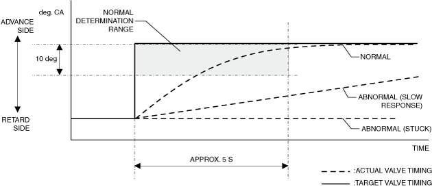
• P0011:00: For the advance amount from the maximum intake valve retard position, a condition in which the actual advance amount is larger than the target value continues for a specified period of time.
• P0012:00: For the advance amount from the maximum intake valve retard position, a condition in which the actual advance amount is smaller than the target value continues for a specified period of time.
Preconditions
• Battery voltage: above 11 V*1
• Engine speed: 5,000 rpm or less*1
• Engine coolant temperature: 20 °C {68 °F} or more*1
• The following DTCs are not detected:
-
― P0010:00, P0335:00 and P0340:00
*1: Standard can be verified by displaying PIDs using M-MDS
Malfunction determination period
• 5 s period
Drive cycle
• 1
Self test type
• CMDTC self test
Sensor used
• CKP sensor
• Intake CMP sensor
Fail-safe function
• Limits intake air amount
• Inhibits the boost system.
• Stops the EGR control.
Vehicle status when DTCs are output
• Not applicable
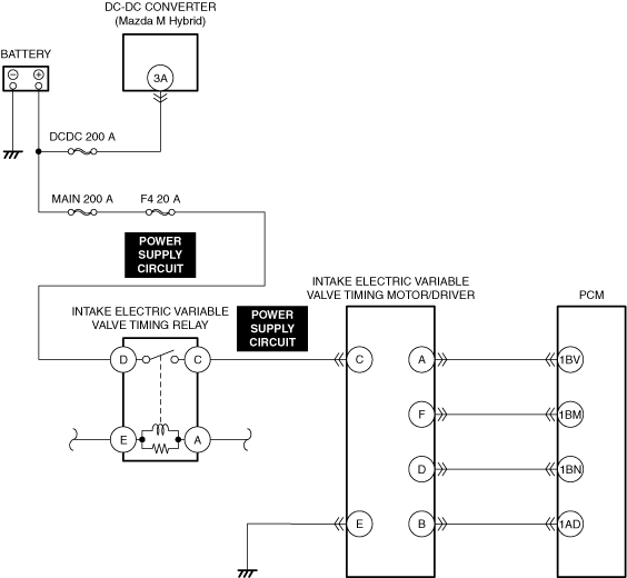
Possible cause
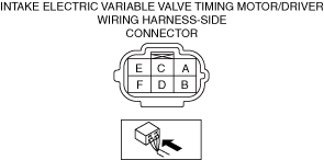
• Intake electric variable valve timing motor/driver connectors or terminals malfunction
• Short to ground or open circuit in intake electric variable valve timing relay power supply circuit
• Short to ground in intake electric variable valve timing motor/driver power supply circuit
• Open circuit in intake electric variable valve timing motor/driver power supply circuit
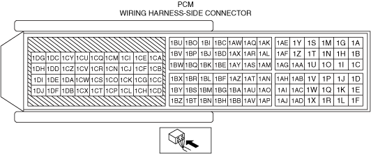
• PCM connector or terminals malfunction
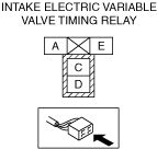
• Intake electric variable valve timing relay malfunction
• Intake electric variable valve timing motor malfunction
• Intake electric variable valve timing actuator malfunction
-
― Intake electric variable valve timing actuator is stuck in advanced position― Intake electric variable valve timing actuator is stuck in retarded position
• Timing chain malfunction
-
― Poor assembly of timing chain― Looseness or jumping
• Mis-detection of intake CMP sensor
• Mis-detection of CKP sensor
• PCM malfunction