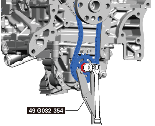
49 G032 354
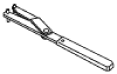
Adjust wrench
TIMING CHAIN REMOVAL/INSTALLATION [SKYACTIV-X 2.0]
id0110hf801000
Special service tool (SST)
|
49 G032 354
Adjust wrench
|
|
Replacement part
|
Oil jet
Quantity: 1
Location of use: Cylinder block
|
1. Perform the [Fuel Line Safety Procedure] referring to [BEFORE SERVICE PRECAUTION]. (See BEFORE SERVICE PRECAUTION [SKYACTIV-X 2.0].)
2. Disconnect the negative battery terminal. (See NEGATIVE BATTERY TERMINAL DISCONNECTION/CONNECTION [(E)].)
3. Remove the engine cover. (See ENGINE COVER REMOVAL/INSTALLATION [SKYACTIV-X 2.0])
4. Remove the following parts. (See SIDE WALL REMOVAL/INSTALLATION [SKYACTIV-X 2.0].)
5. Drain the engine oil. (See ENGINE OIL REPLACEMENT [SKYACTIV-X 2.0].)
6. Remove the following parts as a single unit. (See AIR CLEANER REMOVAL/INSTALLATION [SKYACTIV-X 2.0].)
7. Remove the resonance chamber. (See AIR CLEANER REMOVAL/INSTALLATION [SKYACTIV-X 2.0].)
8. To remove the cylinder head cover, remove the following parts.
9. Remove the cylinder head cover. (See CYLINDER HEAD COVER REMOVAL/INSTALLATION [SKYACTIV-X 2.0].)
10. Remove the rear housing. (See CYLINDER HEAD COVER REMOVAL/INSTALLATION [SKYACTIV-X 2.0].)
11. To remove the engine rear cover (upper), remove the following parts.
12. Remove the engine rear cover (upper). (See ENGINE REAR COVER REMOVAL/INSTALLATION [SKYACTIV-X 2.0])
13. Remove the front crossmember and No.1 engine mount rubber as a single unit. (See FRONT CROSSMEMBER REMOVAL/INSTALLATION [(E)].)
14. Remove the transaxle. (See MANUAL TRANSAXLE REMOVAL/INSTALLATION [C66M-R (SKYACTIV-X 2.0)].(MTX_2WD)) (See MANUAL TRANSAXLE REMOVAL/INSTALLATION [C66MX-R (SKYACTIV-X 2.0)].(MTX_AWD)) (See AUTOMATIC TRANSAXLE REMOVAL/INSTALLATION [ET6A-EL (SKYACTIV-X 2.0)].(ATX_2WD)) (See AUTOMATIC TRANSAXLE REMOVAL/INSTALLATION [ET6AX-EL (SKYACTIV-X 2.0)].(ATX_AWD))
15. Remove the flywheel (MTX) or drive plate (ATX). (See CLUTCH UNIT REMOVAL/INSTALLATION [C66M-R, C66MX-R]. (MTX)) (See DRIVE PLATE REMOVAL/INSTALLATION [ET6A-EL, ET6AX-EL (E)]. (ATX))
16. Remove the engine rear cover (lower). (See ENGINE REAR COVER REMOVAL/INSTALLATION [SKYACTIV-X 2.0])
17. Remove the oil pan. (See OIL PAN REMOVAL/INSTALLATION [SKYACTIV-X 2.0])
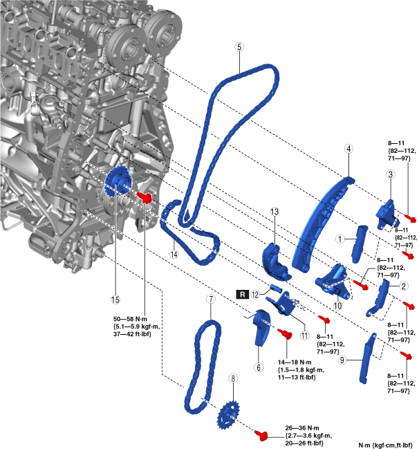
18. Remove using the procedure shown in the figure.
19. Install in the reverse order of removal.
20. Add engine oil to the specified level. (See ENGINE OIL REPLACEMENT [SKYACTIV-X 2.0].)
21. Start the engine and inspect and adjust the following:
am3zzw00038148
|
|
1
|
Chain guide No.1
|
|
2
|
Chain guide No.2
|
|
3
|
Chain tensioner No.1
|
|
4
|
Tensioner arm No.1
|
|
5
|
Timing chain No.1
|
|
6
|
Chain tensioner No.3
|
|
7
|
Oil pump chain
|
|
8
|
Oil pump driven sprocket
|
|
9
|
Chain guide No.3
|
|
10
|
Chain tensioner No.2
|
|
11
|
Chain guide No.4
|
|
12
|
Oil jet
|
|
13
|
Tensioner arm No.2
|
|
14
|
Timing chain No.2
|
|
15
|
High pressure fuel pump driven sprocket
|
Timing Chain No.1 Removal Note
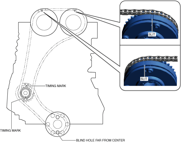
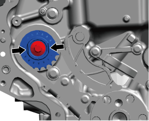
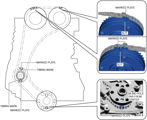
1. Rotate the crankshaft clockwise and align the slits on the actuators with the timing marks as shown in the figure to set cylinder No.1 to top dead center (TDC).
am3zzw00038149
|
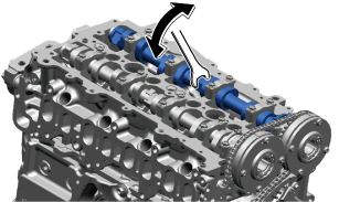
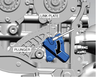
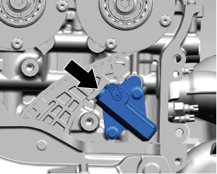
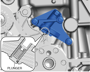
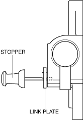
2. While moving the exhaust camshaft back and forth in the direction of the arrows using a wrench on the cast hexagon part, press down on the link plate of the timing chain tensioner with a thin flathead screwdriver (precision screwdriver) to unlock the plunger.
a59cjw00001954
|
am3zzw00038150
|
3. While holding down the link plate, slowly push the plunger back in the direction shown in the figure.
a59cjw00001968
|
4. Remove the screwdriver from the link plate with the plunger still pushed down.
5. Relieve some of the force from the plunger and move it back and forth 2—3 mm {0.08—0.11 in}.
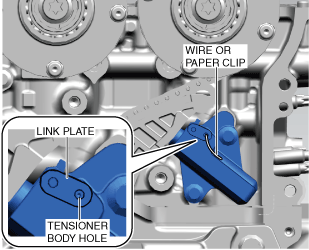
6. Insert a wire or paper clip with an approx. diameter of 1.5 mm {0.059 in} into the tensioner body at the point where the hole in the link plate overlaps the hole in the tensioner body to secure the link plate and lock the plunger.
am3zzw00038151
|
7. Remove chain guide No.1.
8. Remove chain guide No.2.
9. Remove chain tensioner No.1.
10. Remove tensioner arm No.1.
11. Remove timing chain No.1.
Oil Pump Driven Sprocket Removal Note
1. Remove chain tensioner No.3.
2. Install the SST to the oil pump driven sprocket to lock it against rotation.
a59cjw00001998
|
3. Remove the oil pump driven sprocket installation bolt.
4. Remove the oil pump chain and the oil pump driven sprocket as a single unit.
Timing Chain No.2 Removal Note
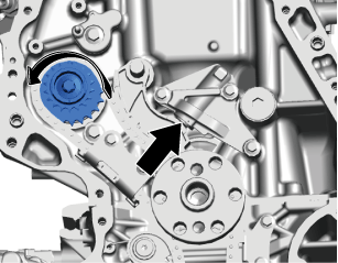
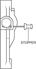
1. Rotate the parts of the width across flats of the high pressure fuel pump driven sprocket in the direction of the arrow using a wrench, and press in the plunger of chain tensioner No.2.
a59cjw00001972
|
2. Insert a wire or paper clip with an approx. diameter of 1.2 mm {0.047 in} at the point where the groove of the plunger overlaps the hole of the tensioner body to secure the plunger.
am3zzw00038152
|
3. Secure the parts of the width across flats of the high pressure fuel pump driven sprocket using a wrench to remove the high pressure fuel pump driven sprocket installation bolt.
a59cjw00001974
|
4. Remove chain tensioner No.2.
5. Remove chain guide No.4.
6. Remove tensioner arm No.2.
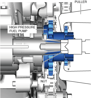
7. Install the M10 nut (width across flats without flange 13 mm {0.051 in} type) to the inner side of the high pressure fuel pump driven sprocket.
8. Install the puller to the outer side of the high pressure fuel pump driven sprocket.
am3zzw00035598
|
9. Remove timing chain No.2 and the high pressure fuel pump driven sprocket as a single unit.
Timing Chain No.2 Installation Note
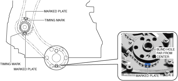
1. Align the marked plate of timing chain No.2 with the tooth of the crankshaft sprocket in the direction of the hole on the crankshaft flange shown in the figure.
am3zzw00038153
|
2. Align the timing marks as shown in the figure and install timing chain No.2 and the high pressure fuel pump driven sprocket as a single unit.
3. Install tensioner arm No.2.
4. Install chain guide No.4.
5. Install chain tensioner No.2.
6. Secure the parts of the width across flats of the high pressure fuel pump driven sprocket using a wrench, and tighten the high pressure fuel pump driven sprocket installation bolt.
a59cjw00001974
|
7. After installing chain tensioner No.2, remove the installed wire or paper clip and apply tension to the timing chain.
am3zzw00038154
|
Oil Pump Driven Sprocket Installation Note
1. Install the oil pump driven sprocket and the oil pump chain as a single unit.
2. Install the SST to the oil pump driven sprocket to lock it against rotation.
a59cjw00001998
|
3. Tighten the oil pump driven sprocket installation bolt.
4. Install chain tensioner No.3.
Timing Chain No.1 Installation Note
1. Install timing chain No.1 while aligning each sprocket with the timing chain marked plates as shown in the figure.
am3zzw00038155
|
2. Install chain tensioner No.1.
3. Install tensioner arm No.1.
4. Install chain guide No.2.
5. Install chain guide No.1.
6. Remove the wire or paper clip installed to chain tensioner No.1 and apply tension to the timing chain.
am3zzw00038156
|
7. Inspect the timing chain for looseness.
8. Verify that the alignment marks on each sprocket and the timing chain are aligned.