|
1
|
INSPECT POWER SUPPLY
• Access the VPWR PID using the M-MDS.
• Verify the VPWR PID value.
• Is the VPWR PID value B+?
|
Yes
|
Go to the next step.
|
|
No
|
Inspect the following:
• Battery connection
-
― If there is any malfunction:
-
• Repair or replace the malfunctioning location, then repeat this step.
|
|
2
|
DETERMINE IF MALFUNCTION CAUSE IS IMMOBILIZER SYSTEM OR OTHER
• Are any of the following conditions present?
-
― Engine does not start completely.
― PCM DTC P1260:00 is displayed.
|
Yes
|
Both conditions present:
• Go to Step 5.
|
|
No
|
Either or other condition present:
• Go to the next step.
|
|
3
|
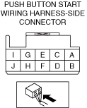
INSPECT PUSH BUTTON START CONNECTOR CONNECTION
• Inspect the connection of push button start connector.
• Is the push button start connector securely connected to the coil antenna?
|
Yes
|
Go to the next step.
|
|
No
|
Reconnect the push button start securely, then repeat from Step 1.
|
|
4
|
DETERMINE IF MALFUNCTION CAUSE IS INSTRUMENT CLUSTER OR OTHER
• Switch the ignition ON (engine off).
• Does the security indicator light illuminate?
|
Yes
|
Go to the next step.
|
|
No
|
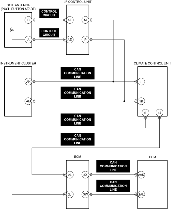
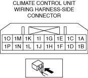
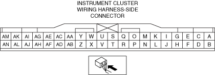
Inspect the wiring harness between the following terminals:
• Instrument cluster terminal AK—Climate control unit terminal 1I
• Instrument cluster terminal AM—Climate control unit terminal 1K
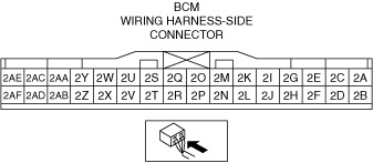
• Climate control unit terminal 1J—Body control module (BCM) terminal 2L
• Climate control unit terminal 1L—Body control module (BCM) terminal 2J
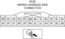
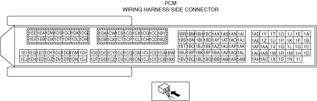
• Body control module (BCM) terminal 3W—PCM terminal 2AL
• Body control module (BCM) terminal 3X—PCM terminal 2AK
-
― If there is any malfunction:
-
• Repair or replace the malfunctioning location and perform the repair completion verification.
• Inspect the instrument cluster
-
― If there is any malfunction:
-
• Repair or replace the malfunctioning location and perform the repair completion verification.
|
|
5
|
VERIFY IMMOBILIZER SYSTEM DTC
• Perform the DTC inspection for the body control module (BCM).
• Are any DTCs displayed?
|
Yes
|
Repair the malfunctioning location according to the applicable DTC troubleshooting.
|
|
No
|
Go to the next step.
|
|
6
|
DETERMINE IF MALFUNCTION CAUSE IS i-stop SYSTEM OR OTHER
• Verify the symptom.
• Does the engine not restart while the i-stop function is operating?
|
Yes
|
Perform the symptom troubleshooting "ENGINE DOES NOT RESTART".
|
|
No
|
Go to the next step.
|
|
7
|
VERIFY PCM DTC
• Perform the DTC inspection for the PCM.
• Are any continuous memory DTCs present?
|
Yes
|
Continuous memory DTC is displayed:
• Repair the malfunctioning location according to the applicable DTC troubleshooting.
Communication error message is displayed:
• Go to the next step.
|
|
No
|
Go to Step 13.
|
|
8
|
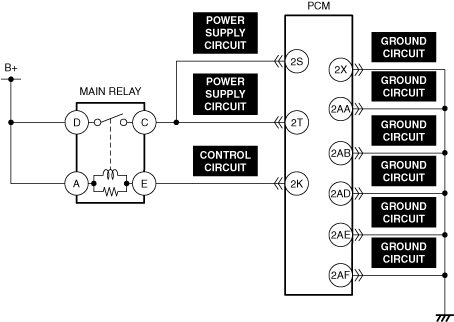
INSPECT MAIN RELAY CONTROL CIRCUIT FOR OPEN CIRCUIT
• Inspect the applicable circuit for open circuit.
• Is the circuit normal?
|
Yes
|
Go to the next step.
|
|
No
|
Repair or replace the malfunctioning location and perform the repair completion verification.
|
|
9
|
INSPECT PCM POWER SUPPLY CIRCUIT FOR OPEN CIRCUIT
• Inspect the applicable circuit for open circuit.
• Is the circuit normal?
|
Yes
|
Go to the next step.
|
|
No
|
Repair or replace the malfunctioning location and perform the repair completion verification.
|
|
10
|
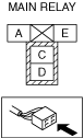
INSPECT MAIN RELAY FOR MALFUNCTION
• Inspect the applicable part.
• Is the part normal?
|
Yes
|
Go to the next step.
|
|
No
|
Repair or replace the malfunctioning location and perform the repair completion verification.
|
|
11
|
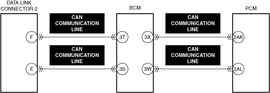
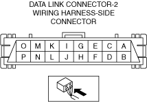
INSPECT CAN COMMUNICATION LINE BETWEEN DLC-2 AND PCM FOR OPEN CIRCUIT
• Inspect the applicable circuit for open circuit.
• Is the circuit normal?
|
Yes
|
Go to the next step.
|
|
No
|
Repair or replace the malfunctioning location and perform the repair completion verification.
|
|
12
|
INSPECT PCM GROUND CIRCUIT FOR OPEN CIRCUIT
• Inspect the applicable circuit for open circuit.
• Is the circuit normal?
|
Yes
|
Go to the next step.
|
|
No
|
Repair or replace the malfunctioning location and perform the repair completion verification.
|
|
13
|
DETERMINE IF MALFUNCTION CAUSE IS STARTER RELAY CONTROL CIRCUIT OR OTHER
• Crank the engine.
• Is a clicking sound heard from the starter relay?
|
Yes
|
Go to Step 25.
|
|
No
|
ATX:
• Go to Step 17.
MTX:
• Go to the next step.
|
|
14
|
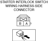
DETERMINE IF MALFUNCTION CAUSE IS STARTER INTERLOCK SWITCH OR OTHER
• Switch the ignition off.
• Short the starter interlock switch terminals A and B (wiring harness-side) using a jumper wire.
• Crank the engine.
• Does the engine start?
|
Yes
|
Inspect the starter interlock switch.
• If there is any malfunction:
-
― Replace the starter interlock switch and perform the repair completion verification.
• If there is no malfunction:
-
― Go to the next step.
|
|
No
|
Go to the next step.
|
|
15
|
INSPECT STARTER INTERLOCK SWITCH CONNECTOR FOR MALFUNCTION
• Inspect the applicable connector and terminal.
• Are the connector and terminal normal?
|
Yes
|
Go to the next step.
|
|
No
|
Repair or replace the malfunctioning location and perform the repair completion verification.
|
|
16
|
INSPECT STARTER INTERLOCK SWITCH GROUND CIRCUIT FOR OPEN CIRCUIT
• Inspect the applicable circuit for open circuit.
• Is the circuit normal?
|
Yes
|
Go to Step 20.
|
|
No
|
Repair or replace the malfunctioning location and perform the repair completion verification.
|
|
17
|
VERIFY TCM DTCs
• Perform the DTC inspection for the TCM.
• Are any DTCs displayed?
|
Yes
|
Repair the malfunctioning location according to the applicable DTC troubleshooting.
|
|
No
|
Go to the next step.
|
|
18
|
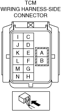
INSPECT TCM CONNECTOR FOR MALFUNCTION
• Inspect the applicable connector and terminal.
• Are the connector and terminal normal?
|
Yes
|
Go to the next step.
|
|
No
|
Repair or replace the malfunctioning location and perform the repair completion verification.
|
|
19
|
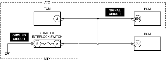
INSPECT TCM SIGNAL CIRCUIT FOR OPEN CIRCUIT
• Inspect the applicable circuit for open circuit.
• Is the circuit normal?
|
Yes
|
Go to the next step.
|
|
No
|
Repair or replace the malfunctioning location and perform the repair completion verification.
|
|
20
|
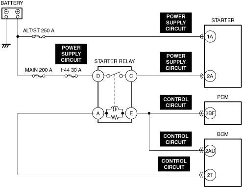
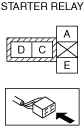
INSPECT STARTER RELAY FOR MALFUNCTION
• Inspect the applicable part.
• Is the part normal?
|
Yes
|
Go to the next step.
|
|
No
|
Repair or replace the malfunctioning location and perform the repair completion verification.
|
|
21
|
INSPECT BODY CONTROL MODULE (BCM) CONNECTOR FOR MALFUNCTION
• Inspect the applicable connector and terminal.
• Are the connector and terminal normal?
|
Yes
|
Go to the next step.
|
|
No
|
Repair or replace the malfunctioning location and perform the repair completion verification.
|
|
22
|
INSPECT PCM CONNECTOR FOR MALFUNCTION
• Inspect the applicable connector and terminal.
• Are the connector and terminal normal?
|
Yes
|
Go to the next step.
|
|
No
|
Repair or replace the malfunctioning location and perform the repair completion verification.
|
|
23
|
INSPECT STARTER RELAY CONTROL CIRCUIT FOR SHORT TO GROUND
• Inspect the applicable circuit for a short to ground.
• Is the circuit normal?
|
Yes
|
Go to the next step.
|
|
No
|
Repair or replace the malfunctioning location and perform the repair completion verification.
|
|
24
|
INSPECT STARTER RELAY CONTROL CIRCUIT FOR OPEN CIRCUIT
• Inspect the applicable circuit for open circuit.
• Is the circuit normal?
|
Yes
|
Inspect the body control module (BCM).
• If there is any malfunction:
-
― Replace the body control module (BCM) and perform the repair completion verification.
• If there is no malfunction:
-
― Replace the control valve body and perform the repair completion verification.
|
|
No
|
Repair or replace the malfunctioning location and perform the repair completion verification.
|
|
25
|
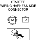
INSPECT STARTER CONNECTOR FOR MALFUNCTION
• Inspect the applicable connector and terminal.
• Are the connector and terminal normal?
|
Yes
|
Go to the next step.
|
|
No
|
Repair or replace the malfunctioning location and perform the repair completion verification.
|
|
26
|
DETERMINE IF MALFUNCTION CAUSE IS STARTER OR OTHER
• Verify that the starter connector is disconnected.
• Crank the engine.
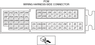
• Measure the voltage at the starter terminal 2A (wiring harness-side)
• Is the voltage B+?
|
Yes
|
Go to Step 30.
|
|
No
|
Go to the next step.
|
|
27
|
INSPECT STARTER RELAY POWER SUPPLY CIRCUIT FOR SHORT TO GROUND AND OPEN CIRCUIT
• Inspect the power supply circuit for an open circuit and short to ground.
• Is the circuit normal?
|
Yes
|
Go to the next step.
|
|
No
|
Repair or replace the malfunctioning location and perform the repair completion verification.
|
|
28
|
INSPECT POWER SUPPLY CIRCUIT BETWEEN STARTER RELAY AND STARTER FOR SHORT TO GROUND
• Inspect the applicable circuit for a short to ground.
• Is the circuit normal?
|
Yes
|
Go to the next step.
|
|
No
|
Repair or replace the malfunctioning location and perform the repair completion verification.
|
|
29
|
INSPECT POWER SUPPLY CIRCUIT BETWEEN STARTER RELAY AND STARTER FOR OPEN CIRCUIT
• Inspect the applicable circuit for open circuit.
• Is the circuit normal?
|
Yes
|
Go to the next step.
|
|
No
|
Repair or replace the malfunctioning location and perform the repair completion verification.
|
|
30
|
INSPECT POWER SUPPLY CIRCUIT BETWEEN BATTERY AND STARTER FOR SHORT TO GROUND AND OPEN CIRCUIT
• Inspect the power supply circuit for an open circuit and short to ground.
• Is the circuit normal?
|
Yes
|
Go to the next step.
|
|
No
|
Repair or replace the malfunctioning location and perform the repair completion verification.
|
|
31
|
INSPECT STARTER FOR MALFUNCTION
• Inspect the applicable part.
• Is the part normal?
|
Yes
|
Go to the next step.
|
|
No
|
Repair or replace the malfunctioning location and perform the repair completion verification.
|
|
32
|
INSPECT IMMOBILIZER SYSTEM RELATED CIRCUIT
• Inspect the following wiring harness and connectors:
-
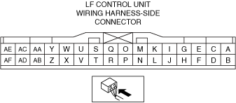
― Between push button start terminal B and LF control unit terminal AF
― Between push button start terminal A and LF control unit terminal AE
― Between LF control unit terminal M and climate control unit terminal 1I
― Between LF control unit terminal P and climate control unit terminal 1K
― Between climate control unit terminal 1J and body control module (BCM) terminal 2L
― Between climate control unit terminal 1L and body control module (BCM) terminal 2J
― Between body control module (BCM) terminal 3X and PCM terminal 2AK
― Between body control module (BCM) terminal 3W and PCM terminal 2AL
• Is there any malfunction?
|
Yes
|
Repair or replace the malfunctioning location and perform the repair completion verification.
|
|
No
|
Go to the next step.
|
|
33
|
VERIFY PRESENT MALFUNCTION DTC
• Perform the KOEO self test.
• Are any DTCs displayed?
|
Yes
|
Repair the malfunctioning location according to the applicable DTC troubleshooting.
|
|
No
|
Go to the next step.
|
|
34
|
DETERMINE IF MALFUNCTION CAUSE IS BASE ENGINE OR OTHER
• Inspect for a seized flywheel (MTX) or drive plate (ATX).
• Is the flywheel (MTX) or drive plate (ATX) seized?
|
Yes
|
Repair or replace the malfunctioning location and perform the repair completion verification.
|
|
No
|
Base engine malfunction or engine damage during compression due to liquid (such as water, fuel, or engine oil) penetration into cylinder.
• Overhaul or replace the engine.
|
|
Repair completion verification 1
|
VERIFY THAT VEHICLE IS REPAIRED
• Install/connect the part removed/disconnected during the troubleshooting procedure.
• Has the malfunction symptom been eliminated?
|
Yes
|
Complete the symptom troubleshooting. (Explain contents of repair to customer)
|
|
No
|
Refer to the controller area network (CAN) malfunction diagnosis flow to inspect for a CAN communication error.
• If the CAN communication is normal, perform the diagnosis from Step 1.
-
― If the malfunction recurs, go to the next step.
|
|
Repair completion verification 2
|
VERIFY IF MALFUNCTION IS CAUSED BY NOT PERFORMING PCM REPROGRAMMING
• Verify repair information and verify that there is a new calibration in the PCM.
• Is there a new calibration in the PCM?
|
Yes
|
Perform the PCM reprogramming and verify if the malfunction symptom was corrected.
• If the malfunction recurs, replace the PCM.
|
|
No
|
Replace the PCM.
|