CONTROL VALVE BODY REMOVAL/INSTALLATION [ET6A-EL, ET6AX-EL (E)]
CONTROL VALVE BODY REMOVAL/INSTALLATION [ET6A-EL, ET6AX-EL (E)]
id0517n31180y3
Replacement Part
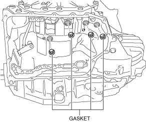
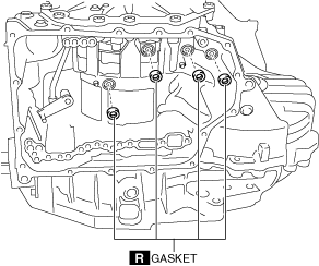
Gasket
Quantity: 4
Location of use: Transaxle case
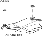
O-ring
Quantity: 2
Location of use: Oil strainer
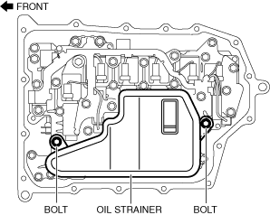
Oil strainer
Quantity: 1
Location of use: Control valve body
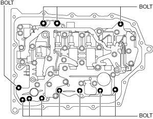
Bolt
Quantity: 16
Location of use: Oil pan
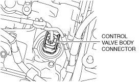
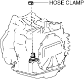
Hose clamp
Quantity: 1
Location of use: Control valve body
—
Oil and Chemical Type
Sealant
Type: TB1217E or equivalent
On-Vehicle Removal
Warning
• A hot transaxle and ATF can cause severe burns. Turn off the engine and wait until they are cool.
• Using compressed air can cause dirt and other particles to fly out, causing injury to the eyes. Wear protective eyeglasses whenever using compressed air.
• Placing the control valve body connector side pointed downward could damage the control valve body connector part or sensor. If the servicing can only be performed by pointing the control valve body connector side downward, spread shock-absorbing material, which does not produce dust or foreign matter, and place the control valve body connector part and sensor on the table so that they do not directly contact the table.
am3zzw00022368
• Always bleed the air from the electric AT oil pump oil passage after replacing the control valve body. If air is in the oil passage of the electric AT oil pump, it could cause a malfunction. (With electric AT oil pump)
• Make sure that your hand does not touch the terminal as the connector terminal could be damaged.
• Water or foreign matter entering the connector can cause a poor connection or corrosion. Be careful not allow water droplets or foreign matter to get on the connector when disconnecting it.
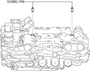
2. Install the dowel pin to the control valve body.
Note
• Oil with a color different from the genuine ATF may be adhered to a new control valve body.
• If the dowel pin remains in the transaxle case, remove the dowel pin from the transaxle case and install the dowel pin to the control valve body.
am3uuw00009186
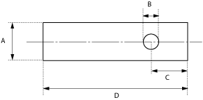
3. Prepare a plastic plate of the size indicated in the figure.
Note
• Use a plastic plate made of material that is not too hard.
ac5wzw00003738
A: 20 mm {0.79 in}
B: φ8 mm {0.3 in}
C: 15 mm {0.59 in}
D: 65 mm {2.6 in}
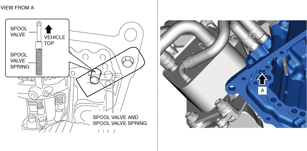
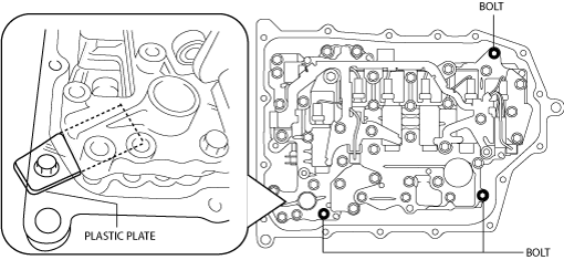
4. Insert the spool valve and the spool valve spring into the transaxle case, and hold the spool valve and the spring using the plastic plate prepared in Step 3 as shown in the figure so that they do not fall off.
am3zzw00032319
5. Install the control valve body using the following procedure.
Caution
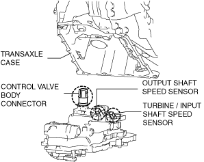
• Install the control valve body so that the turbine/input shaft speed sensor, output shaft speed sensor, and control valve body connector do not contact the transaxle case.
am3zzw00022374
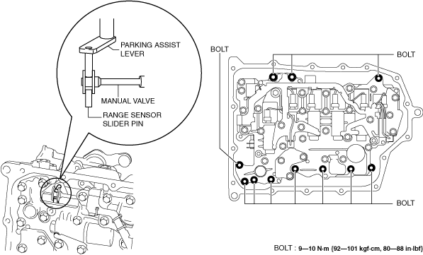
(1) Engage the parking assist lever component on both surfaces of the manual valve.
ac5wzw00006139
(2) Temporarily install the control valve body installation bolts at three locations so that the plastic plate installed in Step 4 can be removed.
ac5wzw00003741
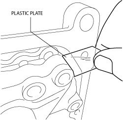
(3) Remove the plastic plate.
Caution
• Because the control valve body may be damaged if foreign material penetrates it, carefully remove the plastic plate preventing foreign material from penetrating the control valve body.
ac5wzw00003742
(4) Install the control valve body.
am3zzw00031977
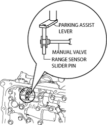
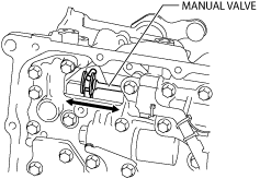
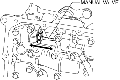
6. Move the manual valve in both directions of the arrow and verify that the manual valve is correctly connected to the parking assist lever component and the slider pin for the range sensor.
ac5wzw00004566
Note
• If the manual valve only moves in the gap between the parking assist lever component surface and the manual valve surface, the manual valve and the parking assist lever component are correctly engaged.
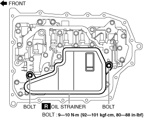
7. Install the new oil strainer O-rings.
am3zzw00022377
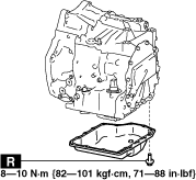
8. Install the new oil strainer.
am3zzw00031978
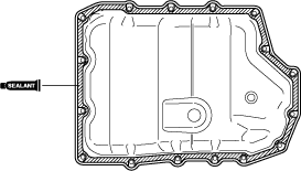
9. Apply a light coat of silicon sealant (TB1217E or equivalent) to the contact surfaces of the oil pan and transaxle case.
am3uuw00008289
Caution
• Clean any remaining silicone sealant on the contact surface of the transaxle case and oil pan, and degrease the sealant area. Otherwise, oil could leak.
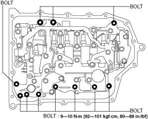
10. Install the oil pan with new bolts before the applied sealant starts to harden.
2. Install the dowel pin to the control valve body.
am3uuw00009186
Note
• Oil with a color different from the genuine ATF may be adhered to a new control valve body.
• If the dowel pin remains in the transaxle case, remove the dowel pin from the transaxle case and install the dowel pin to the control valve body.
3. Install the control valve body so that the parking assist lever component is engaged in the gap between the two surfaces of the spool part of the manual valve.
Caution
• Install the control valve body so that the turbine/input shaft speed sensor, output shaft speed sensor, and control valve body connector do not contact the transaxle case.
am3zzw00022374
am3zzw00031979
4. Move the manual valve in both directions of the arrow and verify that the manual valve is correctly connected to the parking assist lever component and the slider pin for the range sensor.
am3zzw00022376
Note
• If the manual valve only moves in the gap between the parking assist lever component surface and the manual valve surface, the manual valve and the parking assist lever component are correctly engaged.
5. Install the new oil strainer O-rings.
am3zzw00022377
6. Install the new oil strainer.
am3zzw00031978
7. Apply a light coat of silicone sealant (TB1217E or equivalent) to the contact surfaces of the oil pan and transaxle case.
am3uuw00008289
Caution
• Clean any remaining silicone sealant on the contact surface of the transaxle case and oil pan, and degrease the sealant area. Otherwise, oil could leak.
8. Install the oil pan with new bolts before the applied sealant starts to harden.