|
1
|
VERIFY PCM DTC
• Perform the DTC inspection for the PCM.
• Are any DTCs displayed?
|
Yes
|
Repair the malfunctioning location according to the applicable DTC troubleshooting.
|
|
No
|
Go to the next step.
|
|
2
|
VERIFY BODY CONTROL MODULE (BCM) DTC
• Perform the DTC inspection for the body control module (BCM).
• Are any DTCs displayed?
|
Yes
|
Repair the malfunctioning location according to the applicable DTC troubleshooting.
|
|
No
|
Go to the next step.
|
|
3
|
VERIFY DASH-ELECTRICAL SUPPLY UNIT DTC
• Perform the DTC inspection for the dash-electrical supply unit.
• Are any DTCs displayed?
|
Yes
|
Repair the malfunctioning location according to the applicable DTC troubleshooting.
|
|
No
|
Go to the next step.
|
|
4
|
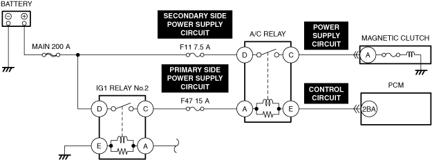
DETERMINE IF MALFUNCTION CAUSE IS A/C RELAY CONTROL SIGNAL OR A/C REQUEST SIGNAL
• Access the PCM simulation item A/C_RLY using the M-MDS.
• Start the engine and idle it.
• Turn the A/C_RLY PID to ON from OFF using the M-MDS simulation function.
• Is the magnetic clutch engaged?
|
Yes
|
Go to the next step.
|
|
No
|
Go to Step 7.
|
|
5
|
DETERMINE IF MALFUNCTION CAUSE IS REFRIGERANT PRESSURE SENSOR OR OTHER
• Access the PCM PID A/C_REQ using the M-MDS.
• Monitor the A/C_REQ PID while turning on and off the air conditioner using the switch on the control panel.
• Is the A/C_REQ PID value normal?
|
Yes
|
Go to the next step.
|
|
No
|
Go to Step 7.
|
|
6
|
INSPECT REFRIGERANT PRESSURE SENSOR FOR MALFUNCTION
• Inspect the applicable part.
• Is the part normal?
|
Yes
|
Inspect the following:
• Refrigerant charging amount
• A/C compressor seized
-
― If there is any malfunction:
-
• Repair or replace the malfunctioning location and perform the repair completion verification.
|
|
No
|
Repair or replace the malfunctioning location and perform the repair completion verification.
|
|
7
|
DETERMINE IF MALFUNCTION CAUSE IS A/C CONTROL SIGNAL OR MAGNETIC CLUTCH
• Start the engine and idle it.
• Access the PCM simulation item A/C_SW using the M-MDS.
• Turn the A/C_SW PID to ON from OFF using the M-MDS simulation function.
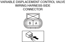
• Measure the voltage at the magnetic clutch terminal A (wiring harness-side).
• Is the voltage 10.5 V or more?
|
Yes
|
Go to the next step.
|
|
No
|
Go to Step 9.
|
|
8
|
INSPECT IF MALFUNCTION CAUSE IS MAGNETIC CLUTCH OR MAGNETIC CLUTCH GROUND CIRCUIT
• Switch the ignition off.
• Disconnect the magnetic clutch connector.
• Inspect for continuity between magnetic clutch terminal A (part-side) and body ground.
• Is there continuity?
|
Yes
|
Inspect the magnetic clutch.
Repair or replace the malfunctioning location and perform the repair completion verification.
|
|
No
|
Inspect the A/C compressor. (poor contact to ground)
• If there is any malfunction:
-
― Repair or replace the malfunctioning location and perform the repair completion verification.
• If there is no malfunction:
-
― Replace the A/C compressor and perform the repair completion verification. (Internal circuit open)
|
|
9
|
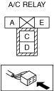
INSPECT A/C RELAY FOR MALFUNCTION
• Inspect the applicable part.
• Is the part normal?
|
Yes
|
Go to the next step.
|
|
No
|
Repair or replace the malfunctioning location and perform the repair completion verification.
|
|
10
|
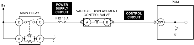
INSPECT VARIABLE DISPLACEMENT CONTROL VALVE POWER SUPPLY CIRCUIT FOR OPEN CIRCUIT
• Inspect the applicable circuit for open circuit.
• Is the circuit normal?
|
Yes
|
Go to the next step.
|
|
No
|
Repair or replace the malfunctioning location and perform the repair completion verification.
|
|
11
|
INSPECT VARIABLE DISPLACEMENT CONTROL VALVE CONTROL CIRCUIT FOR OPEN CIRCUIT
• Inspect the applicable circuit for open circuit.
• Is the circuit normal?
|
Yes
|
Variable displacement control valve can be considered the cause.
Refer to the controller area network (CAN) malfunction diagnosis flow to inspect for a CAN communication error.
• If the CAN communication is normal, perform the diagnosis from Step 1.
-
― If the malfunction recurs, replace the A/C compressor and perform the repair completion verification.
|
|
No
|
Repair or replace the malfunctioning location and perform the repair completion verification.
|
|
Repair completion verification 1
|
VERIFY THAT VEHICLE IS REPAIRED
• Install/connect the part removed/disconnected during the troubleshooting procedure.
• Has the malfunction symptom been eliminated?
|
Yes
|
Complete the symptom troubleshooting. (Explain contents of repair to customer)
|
|
No
|
Refer to the controller area network (CAN) malfunction diagnosis flow to inspect for a CAN communication error.
• If the CAN communication is normal, perform the diagnosis from Step 1.
-
― If the malfunction recurs, go to the next step.
|
|
Repair completion verification 2
|
VERIFY IF MALFUNCTION IS CAUSED BY NOT PERFORMING PCM REPROGRAMMING
• Verify repair information and verify that there is a new calibration in the PCM.
• Is there a new calibration in the PCM?
|
Yes
|
Perform the PCM reprogramming and verify if the malfunction symptom was corrected.
• If the malfunction recurs, replace the PCM.
|
|
No
|
Replace the PCM.
|