 |
ac30zw00003998
OIL COOLER REMOVAL/INSTALLATION [ET6A-EL, ET6AX-EL (SKYACTIV-X 2.0)]
id0517n31175o7
Replacement Part
|
O-ring
Quantity: 2
Location of use: Oil cooler
|
Gasket
Quantity: 2
Location of use: Connector bolt
|
Water Hose
1. Remove the front under cover No.2. (See FRONT UNDER COVER No.2 REMOVAL/INSTALLATION.)
2. Remove the insulator. (See OIL PAN REMOVAL/INSTALLATION [SKYACTIV-X 2.0].)
3. Drain the engine coolant. (See ENGINE COOLANT REPLACEMENT [SKYACTIV-X 2.0].)
4. Remove in the order indicated in the table.
5. Install in the reverse order of removal.
6. Add the engine coolant. (See ENGINE COOLANT REPLACEMENT [SKYACTIV-X 2.0].)
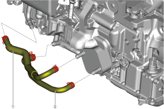
ac30zw00003998
|
|
1
|
Water hose No.1
|
|
2
|
Water hose No.2
|
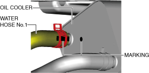
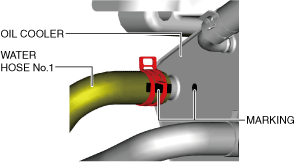
Water hose No.1 (oil cooler side) installation note
1. Install the water hose to the oil cooler as shown in the figure with the hose clamp expanded.
ac30zw00003999
|
2. The hose clamp installation direction is within range A shown in the figure.
ac30zw00004000
|
3. Verify that the hose clamp does not interfere with any other components.
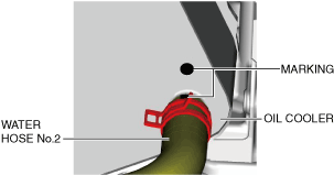
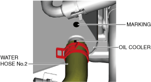
Water hose No.2 (oil cooler side) installation note
1. Install the water hose to the oil cooler as shown in the figure with the hose clamp expanded.
ac30zw00004001
|
2. The hose clamp installation direction is within range A shown in the figure.
ac30zw00004002
|
3. Verify that the hose clamp does not interfere with any other components.
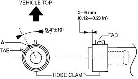
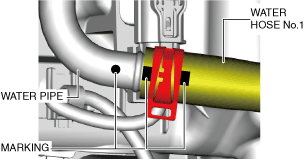
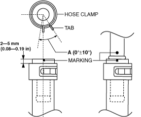
Water hose No.1 (water pipe side) installation note
1. Install the water hose No.1 to the water pipe as shown in the figure with the hose clamp expanded.
am3zzw00032310
|
2. The hose clamp installation direction is within range A shown in the figure.
ac30zw00004003
|
3. Verify that the hose clamp does not interfere with any other components.
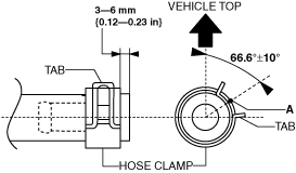
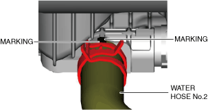
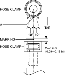
Water hose No.2 (water pipe side) installation note
1. Install the water hose No.2 to the water pipe as shown in the figure with the hose clamp expanded.
am3zzw00032311
|
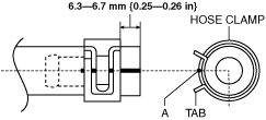
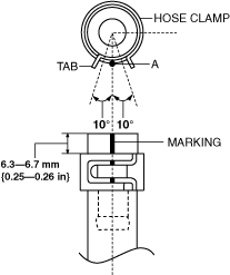
2. Install the hose clamp so that center A of the hose clamp tab is within the range shown in the figure.
ac30zw00004004
|
3. Verify that the hose clamp does not interfere with any other components.
Oil Cooler (without oil hose)
1. Disconnect the negative battery terminal. (See NEGATIVE BATTERY TERMINAL DISCONNECTION/CONNECTION [(E)].)
2. Open the engine cover.
3. Remove the following parts as a single unit. (See AIR CLEANER REMOVAL/INSTALLATION [SKYACTIV-X 2.0].)
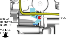
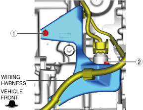
4. Remove the bolts and set the wiring harness and wiring harness brackets in a place which does not interfere with servicing. (See Wiring harness bracket installation note.)
ac30zw00004005
|
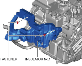
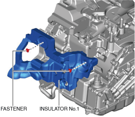
5. Remove the insulator No.1.
ac30zw00004006
|
6. Remove the front under cover No.2. (See FRONT UNDER COVER No.2 REMOVAL/INSTALLATION.)
7. Remove the front under cover No.1. (See FRONT UNDER COVER No.1 REMOVAL/INSTALLATION.)
8. Drain the ATF. (See AUTOMATIC TRANSAXLE FLUID (ATF) REPLACEMENT [ET6A-EL, ET6AX-EL (E)].)
9. Drain the engine coolant. (See ENGINE COOLANT REPLACEMENT [SKYACTIV-X 2.0].)
10. Remove in the order indicated in the table.
11. Install in the reverse order of removal.
12. Add the engine coolant. (See ENGINE COOLANT REPLACEMENT [SKYACTIV-X 2.0].)
13. Add the ATF. (See AUTOMATIC TRANSAXLE FLUID (ATF) REPLACEMENT [ET6A-EL, ET6AX-EL (E)].)
14. Perform the “Mechanical System Test”. (See MECHANICAL SYSTEM TEST [ET6A-EL, ET6AX-EL (E)].)
ac30zw00004007
|
|
1
|
Water hose No.1
|
|
2
|
Water hose No.2
|
|
3
|
Oil cooler
|
|
4
|
O-ring
|
Water hose No.1 (oil cooler side) installation note
1. Install the water hose to the oil cooler as shown in the figure with the hose clamp expanded.
ac30zw00003999
|
2. Install the hose clamp so that center A of the hose clamp tab is within the range shown in the figure.
ac30zw00004000
|
3. Verify that the hose clamp does not interfere with any other components.
Water hose No.2 (oil cooler side) installation note
1. Install the water hose to the oil cooler as shown in the figure with the hose clamp expanded.
ac30zw00004001
|
2. Install the hose clamp so that center A of the hose clamp tab is within the range shown in the figure.
ac30zw00004002
|
3. Verify that the hose clamp does not interfere with any other components.
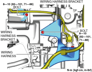
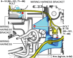
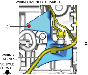
Wiring harness bracket installation note
1. Install the wiring harness bracket.
am3zzw00032534
|
2. Tighten the wiring harness bracket installation bolts in the order shown in the figure.
ac30zw00004008
|
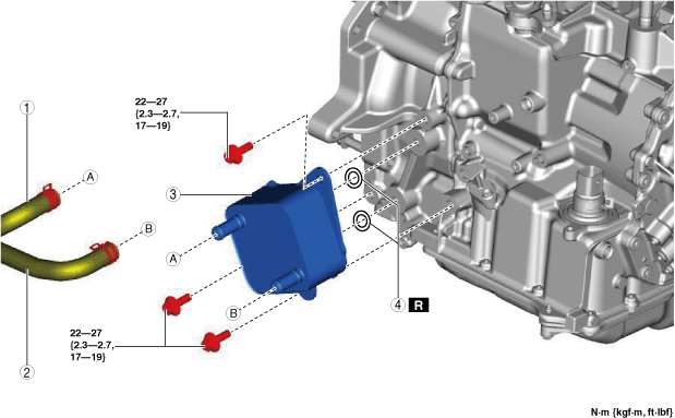
Oil Cooler (With Oil Hose)
1. Disconnect the negative battery terminal. (See NEGATIVE BATTERY TERMINAL DISCONNECTION/CONNECTION [(E)].)
2. Open the engine cover.
3. Remove the left wall (front). (See SIDE WALL REMOVAL/INSTALLATION [SKYACTIV-X 2.0].)
4. Remove the following parts as a single unit. (See AIR CLEANER REMOVAL/INSTALLATION [SKYACTIV-X 2.0].)
5. Remove the bolts and set the wiring harness and wiring harness brackets in a place which does not interfere with servicing. (See Oil hose No.2 (oil cooler side) installation note.)
am3zzw00031970
|
6. Remove the insulator No.1.
am3zzw00031971
|
7. Remove the front under cover No.2. (See FRONT UNDER COVER No.2 REMOVAL/INSTALLATION.)
8. Remove the front under cover No.1. (See FRONT UNDER COVER No.1 REMOVAL/INSTALLATION.)
9. Drain the ATF. (See AUTOMATIC TRANSAXLE FLUID (ATF) REPLACEMENT [ET6A-EL, ET6AX-EL (E)].)
10. Drain the engine coolant. (See ENGINE COOLANT REPLACEMENT [SKYACTIV-X 2.0].)
11. Remove in the order indicated in the table.
12. Install in the reverse order of removal.
13. Add the engine coolant. (See ENGINE COOLANT REPLACEMENT [SKYACTIV-X 2.0].)
14. Add the ATF. (See AUTOMATIC TRANSAXLE FLUID (ATF) REPLACEMENT [ET6A-EL, ET6AX-EL (E)].)
15. Perform the “Mechanical System Test”. (See MECHANICAL SYSTEM TEST [ET6A-EL, ET6AX-EL (E)].)
am3zzw00038220
|
|
1
|
Water hose No.1
|
|
2
|
Water hose No.2
|
|
3
|
Oil cooler assembly
|
|
4
|
O-ring
|
|
5
|
Connector bolt
|
|
6
|
Gasket
|
Water hose No.1 (oil cooler side) installation note
1. Install the water hose to the oil cooler as shown in the figure with the hose clamp expanded.
am3zzw00032530
|
2. The hose clamp installation direction is within range A shown in the figure.
ac30zw00004000
|
3. Verify that the hose clamp does not interfere with any other components.
Water hose No.2 (oil cooler side) installation note
1. Install the water hose to the oil cooler as shown in the figure with the hose clamp expanded.
am3zzw00032309
|
2. The hose clamp installation direction is within range A shown in the figure.
ac30zw00004002
|
3. Verify that the hose clamp does not interfere with any other components.
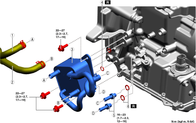
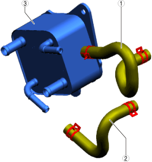
Oil cooler assembly installation note
1. Install the oil hose No.1 to the connector bolt as shown in the figure with the hose clamp expanded.
am3zzw00032314
|
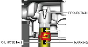
2. Install the hose clamp so that center A of the hose clamp tab is aligned with the marking as shown in the figure.
am3zzw00031975
|
3. Verify that the hose clamp does not interfere with any other components.
4. Install the oil hose No.2 to the connector bolt as shown in the figure with the hose clamp expanded.
am3zzw00032315
|
5. Install the hose clamp so that center A of the hose clamp tab is within the range shown in the figure.
am3zzw00031976
|
6. Verify that the hose clamp does not interfere with any other components.
Wiring harness bracket installation note
1. Install the wiring harness bracket.
am3zzw00032534
|
2. Tighten the wiring harness bracket installation bolts in the order shown in the figure.
am3zzw00032535
|
Oil Hose (With Oil Hose)
1. Remove the oil cooler assembly. (See Oil Cooler (With Oil Hose).)
2. Remove in the order indicated in the table.
3. Install in the reverse order of removal.
am3zzw00038221
|
|
1
|
Oil hose No.1
|
|
2
|
Oil hose No.2
|
|
3
|
Oil cooler
|
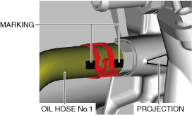
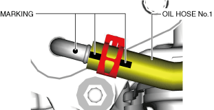
Oil hose No.1 (oil cooler side) installation note
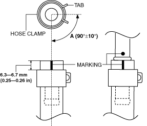
1. Install the oil hose No.1 to the oil cooler as shown in the figure with the hose clamp expanded.
am3zzw00032312
|
2. The hose clamp installation direction is within range A shown in the figure.
am3zzw00031973
|
3. Verify that the hose clamp does not interfere with any other components.
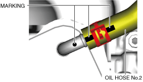
Oil hose No.2 (oil cooler side) installation note
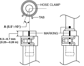
1. Install the oil hose No.2 to the oil cooler as shown in the figure with the hose clamp expanded.
am3zzw00032313
|
2. The hose clamp installation direction is within range A shown in the figure.
am3zzw00031974
|
3. Verify that the hose clamp does not interfere with any other components.