 |
ac30zw00002430
ERROR IS DISPLAYED ON VEHICLE IDENTIFICATION [VEHICLE INFORMATION ACQUISITION] SCREEN [(E)]
id1002x2005400
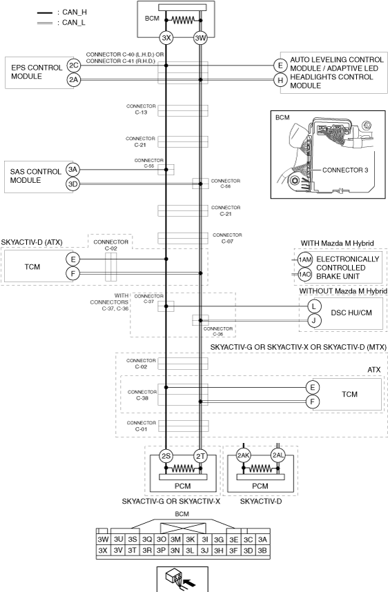
System Wiring Diagram
ac30zw00002430
|
Determination Procedure
|
Step |
Inspection |
Action |
|
|---|---|---|---|
|
1
|
INSPECT FOR SHORT TO GROUND IN CAN-BUS NO.1
• Switch the ignition off.
• Disconnect the negative battery terminal.
• Inspect for continuity at the following terminals:
• Is there continuity?
|
Yes
|
Short to ground in CAN-BUS No.1 has occurred.
Determine the location of a short to ground according to the diagnosis procedure for determining the location of a short to ground in CAN-BUS No.1.
|
|
No
|
Go to the next step.
|
||
|
2
|
INSPECT FOR SHORT TO POWER SUPPLY IN CAN-BUS No.1
• Connect the negative battery terminal.
• Switch the ignition ON (engine off).
• Measure the voltage at body control module (BCM) terminal 3X and 3W.
• Is the voltage between 1.5—3.5 V?
|
Yes
|
Go to the next step.
|
|
No
|
Short to power supply in CAN-BUS No.1 has occurred.
Determine the location of a short to power supply according to the diagnosis procedure for determining the location of a short to power supply in CAN-BUS No.1.
|
||
|
3
|
INSPECT FOR SHORT BETWEEN CIRCUITS IN CAN-BUS No.1
• Measure the voltage at body control module (BCM) terminals 3X and 3W.
• Is the voltage at body control module (BCM) terminals 3X and 3W the same?
|
Yes
|
Short between circuits in CAN-BUS No.1 has occurred.
Determine the location of a short between circuits according to the diagnosis procedure for determining the location of a short between circuits in CAN-BUS No.1.
|
|
No
|
Go to the next step.
|
||
|
4
|
INSPECT FOR OPEN CIRCUIT IN THE WIRING HARNESS BETWEEN PCM AND BODY CONTROL MODULE (BCM)
• Switch the ignition off.
• Disconnect the negative battery terminal.
• Disconnect the EPS control module connector.
• Disconnect the auto leveling control module / adaptive LED headlights control module connector.
• Disconnect the SAS control module connector.
• Disconnect the electronically controlled brake unit / DSC HU/CM connector.
• Disconnect the TCM connector.
• Inspect for continuity at the following terminals:
• Is there continuity?
|
Yes
|
Because the circuit between the PCM and body control module (BCM) is currently normal, go back to the [TROUBLESHOOTING PROCEDURE].
|
|
No
|
• Any of the following malfunctions may have occurred.
|
||