 |
ac30zw00002371
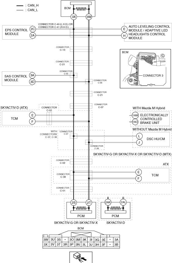
DETERMINING SHORT BETWEEN CIRCUITS LOCATION (CAN-BUS No.1) [(E)]
id1002x2002000
System Wiring Diagram
ac30zw00002371
|
Determination Procedure
|
Step |
Inspection |
Action |
|
|---|---|---|---|
|
1
|
INSPECT BODY CONTROL MODULE (BCM) FOR SHORT BETWEEN CIRCUITS
• Switch the ignition off.
• Disconnect the negative battery terminal.
• Disconnect the connector 3 which has body control module (BCM) terminals 3X and 3W.
• Connect the negative battery terminal.
• Switch the ignition ON (engine off).
• Measure the voltage at body control module (BCM) terminals 3X and 3W (wiring harness side).
• Is the voltage at body control module (BCM) terminals 3X and 3W (wiring harness side) the same?
|
Yes
|
Go to the next step.
|
|
No
|
Replace the body control module (BCM) because there is a short between circuits in the body control module (BCM).
|
||
|
2
|
INSPECT CAN LINE BETWEEN CONNECTOR C-40/C-41 AND BODY CONTROL MODULE (BCM) FOR SHORT BETWEEN CIRCUITS
• Switch the ignition off.
• Disconnect the negative battery terminal.
• Disconnect the connector C-40 (L.H.D.).
• Disconnect the connector C-41 (R.H.D.).
• Connect the connector 3 which has body control module (BCM) terminals 3X and 3W.
• Connect the negative battery terminal.
• Switch the ignition ON (engine off).
• Measure the voltage at body control module (BCM) terminals 3X and 3W.
• Is the voltage at body control module (BCM) terminals 3X and 3W the same?
|
Yes
|
• Repair or replace the wiring harness between the connector C-40 and body control module (BCM) because the wiring harness is shorted between circuits (L.H.D.).
• Repair or replace the wiring harness between the connector C-41 and body control module (BCM) because the wiring harness is shorted between circuits (R.H.D.).
|
|
No
|
Go to the next step.
|
||
|
3
|
INSPECT CAN LINE BETWEEN EPS CONTROL MODULE AND CONNECTOR C-40/C-41 FOR SHORT BETWEEN CIRCUITS
• Switch the ignition off.
• Disconnect the negative battery terminal.
• Inspect for continuity between EPS control module terminals 2C and 2A.
• Is there continuity?
|
Yes
|
Go to the next step.
|
|
No
|
Go to Step 5.
|
||
|
4
|
INSPECT EPS CONTROL MODULE FOR SHORT BETWEEN CIRCUITS
• Disconnect the EPS control module connector.
• Inspect for continuity between EPS control module terminals 2C and 2A(wiring harness side).
• Is there continuity?
|
Yes
|
• Repair or replace the wiring harness between the EPS control module and connector C-40 because the wiring harness is shorted between circuits (L.H.D.).
• Repair or replace the wiring harness between the EPS control module and connector C-41 because the wiring harness is shorted between circuits (R.H.D.).
|
|
No
|
Replace the EPS control module because there is a short between circuits in the EPS control module.
|
||
|
5
|
INSPECT CAN LINE BETWEEN AUTO LEVELING CONTROL MODULE / ADAPTIVE LED HEADLIGHTS CONTROL MODULE AND CONNECTOR C-40/C-41 FOR SHORT BETWEEN CIRCUITS
• Inspect for continuity between auto leveling control module / adaptive LED headlights control module terminals E and H.
• Is there continuity?
|
Yes
|
Go to the next step.
|
|
No
|
Go to Step 7.
|
||
|
6
|
INSPECT AUTO LEVELING CONTROL MODULE / ADAPTIVE LED HEADLIGHTS CONTROL MODULE FOR SHORT BETWEEN CIRCUITS
• Disconnect the auto leveling control module / adaptive LED headlights control module connector.
• Inspect for continuity between auto leveling control module / adaptive LED headlights control module terminals E and H (wiring harness side).
• Is there continuity?
|
Yes
|
• Repair or replace the wiring harness between the auto leveling control module / adaptive LED headlights control module and connector C-40 because the wiring harness is shorted between circuits (L.H.D.).
• Repair or replace the wiring harness between the auto leveling control module / adaptive LED headlights control module and connector C-41 because the wiring harness is shorted between circuits (R.H.D.).
|
|
No
|
Replace the auto leveling control module / adaptive LED headlights control module because there is a short between circuits in the auto leveling control module / adaptive LED headlights control module.
|
||
|
7
|
INSPECT CAN LINE BETWEEN CONNECTOR C-13 AND CONNECTOR C-40/C-41 FOR SHORT BETWEEN CIRCUITS
• Disconnect the connector C-13.
• Connect the connector C-40 (L.H.D.).
• Connect the connector C-41 (R.H.D.).
• Connect the negative battery terminal.
• Switch the ignition ON (engine off).
• Measure the voltage at body control module (BCM) terminals 3X and 3W.
• Is the voltage at body control module (BCM) terminals 3X and 3W the same?
|
Yes
|
• Repair or replace the wiring harness between the connector C-40 and connector C-13 because the wiring harness is shorted between circuits (L.H.D.).
• Repair or replace the wiring harness between the connector C-41 and connector C-13 because the wiring harness is shorted between circuits (R.H.D.).
|
|
No
|
Go to the next step.
|
||
|
8
|
INSPECT CAN LINE BETWEEN CONNECTOR C-21 AND CONNECTOR C-13 FOR SHORT BETWEEN CIRCUITS
• Switch the ignition off.
• Disconnect the negative battery terminal.
• Disconnect the connector C-21.
• Connect the connector C-13.
• Connect the negative battery terminal.
• Switch the ignition ON (engine off).
• Measure the voltage at body control module (BCM) terminals 3X and 3W.
• Is the voltage at body control module (BCM) terminals 3X and 3W the same?
|
Yes
|
Repair or replace the wiring harness between connector C-21 and connector C-13 because the wiring harness is shorted between circuits.
|
|
No
|
Go to the next step.
|
||
|
9
|
INSPECT CAN LINE BETWEEN CONNECTOR C-21 AND PCM FOR SHORT BETWEEN CIRCUITS
• Measure the voltage at PCM terminals 2S and 2T. (SKYACTIV-G or SKYACTIV-X)
• Measure the voltage at PCM terminals 2AK and 2AL. (SKYACTIV-D)
• Is the voltage at PCM terminals 2S and 2T the same? (SKYACTIV-G or SKYACTIV-X)
• Is the voltage at PCM terminals 2AK and 2AL the same? (SKYACTIV-D)
|
Yes
|
Go to Step 13.
|
|
No
|
Go to the next step.
|
||
|
10
|
INSPECT CAN LINE BETWEEN CONNECTOR C-21 AND CONNECTORS C-55, C-56 FOR SHORT BETWEEN CIRCUITS
• Switch the ignition off.
• Disconnect the negative battery terminal.
• Disconnect the connectors C-55, C-56.
• Connect the connector C-21.
• Connect the negative battery terminal.
• Switch the ignition ON (engine off).
• Measure the voltage at body control module (BCM) terminals 3X and 3W.
• Is the voltage at body control module (BCM) terminals 3X and 3W the same?
|
Yes
|
Repair or replace the wiring harness between connector C-21 and connectors C-55, C-56 because the wiring harness is shorted between circuits.
|
|
No
|
Go to the next step.
|
||
|
11
|
INSPECT CAN LINE BETWEEN SAS CONTROL MODULE AND CONNECTORS C-55, C-56 FOR SHORT BETWEEN CIRCUITS
• Measure the voltage at PCM terminals 2S and 2T. (SKYACTIV-G or SKYACTIV-X)
• Measure the voltage at PCM terminals 2AK and 2AL. (SKYACTIV-D)
• Is the voltage at PCM terminals 2S and 2T the same? (SKYACTIV-G or SKYACTIV-X)
• Is the voltage at PCM terminals 2AK and 2AL the same? (SKYACTIV-D)
|
Yes
|
Repair or replace the wiring harness between the connectors C-55, C-56 and connector C-21 because the wiring harness is shorted between circuits.
|
|
No
|
Go to the next step.
|
||
|
12
|
INSPECT SAS CONTROL MODULE FOR SHORT BETWEEN CIRCUITS
• Switch the ignition off.
• Disconnect the negative battery terminal.
• Disconnect the SAS control module connector.
• Inspect for continuity between SAS control module terminals 3A and 3D (wiring harness side).
• Is there continuity?
|
Yes
|
Repair or replace the wiring harness between the SAS control module and connectors C-55, C-56 because the wiring harness is shorted between circuits.
|
|
No
|
Replace the SAS control module because there is a short between circuits in the SAS control module.
|
||
|
13
|
INSPECT CAN LINE BETWEEN CONNECTOR C-07 AND CONNECTOR C-21 FOR SHORT BETWEEN CIRCUITS
• Switch the ignition off.
• Disconnect the negative battery terminal.
• Disconnect the connector C-07.
• Connect the connector C-21.
• Connect the negative battery terminal.
• Switch the ignition ON (engine off).
• Measure the voltage at body control module (BCM) terminals 3X and 3W.
• Is the voltage at body control module (BCM) terminals 3X and 3W the same?
|
Yes
|
Repair or replace the wiring harness between connector C-07 and connector C-21 because the wiring harness is shorted between circuits.
|
|
No
|
• Go to the next step. (SKYACTIV-D (ATX)) (with connectors C-37, C-36)
• Go to Step 20. (SKYACTIV-D (ATX)) (without connectors C-37, C-36)
• Go to Step 24. (SKYACTIV-G or SKYACTIV-X or SKYACTIV-D (MTX)) (with connectors C-37, C-36)
• Go to Step 28. (SKYACTIV-G or SKYACTIV-X or SKYACTIV-D (MTX)) (without connectors C-37, C-36)
|
||
|
14
|
INSPECT CAN LINE BETWEEN CONNECTORS C-37, C-36 AND CONNECTOR C-07 FOR SHORT BETWEEN CIRCUITS
• Switch the ignition off.
• Disconnect the negative battery terminal.
• Disconnect the connectors C-37, C-36.
• Connect the connector C-07.
• Connect the negative battery terminal.
• Switch the ignition ON (engine off).
• Measure the voltage at body control module (BCM) terminals 3X and 3W.
• Is the voltage at body control module (BCM) terminals 3X and 3W the same?
|
Yes
|
Go to Step 17.
|
|
No
|
Go to the next step.
|
||
|
15
|
INSPECT CAN LINE BETWEEN CONNECTOR C-02 AND CONNECTOR C-07 / CONNECTORS C-37, C-36 FOR SHORT BETWEEN CIRCUITS
• Switch the ignition off.
• Disconnect the negative battery terminal.
• Disconnect the connectors C-02.
• Connect the negative battery terminal.
• Switch the ignition ON (engine off).
• Measure the voltage at body control module (BCM) terminals 3X and 3W.
• Is the voltage at body control module (BCM) terminals 3X and 3W the same?
|
Yes
|
Repair or replace the wiring harness between the connector C-02 and connector C-07 / connectors C-37, C-36 because the wiring harness is shorted between circuits.
|
|
No
|
Go to the next step.
|
||
|
16
|
INSPECT TCM FOR SHORT BETWEEN CIRCUITS
• Switch the ignition off.
• Disconnect the negative battery terminal.
• Disconnect the TCM connector.
• Inspect for continuity between TCM terminals E and F (wiring harness side).
• Is there continuity?
|
Yes
|
Repair or replace the wiring harness between the TCM and connector C-02 because the wiring harness is shorted between circuits.
|
|
No
|
Replace the TCM because there is a short between circuits in the TCM.
|
||
|
17
|
INSPECT CAN LINE BETWEEN DSC HU/CM / ELECTRONICALLY CONTROLLED BRAKE UNIT AND CONNECTORS C-37, C-36 FOR SHORT BETWEEN CIRCUITS
• Switch the ignition off.
• Disconnect the negative battery terminal.
• Inspect for continuity between DSC HU/CM terminals L and J. (without Mazda M Hybrid)
• Inspect for continuity between electronically controlled brake unit terminals 1AM and 1AO. (with Mazda M Hybrid)
• Is there continuity?
|
Yes
|
Go to the next step.
|
|
No
|
Go to Step 19.
|
||
|
18
|
INSPECT DSC HU/CM / ELECTRONICALLY CONTROLLED BRAKE UNIT FOR SHORT BETWEEN CIRCUITS
• Disconnect the DSC HU/CM / electronically controlled brake unit connector.
• Inspect for continuity between DSC HU/CM terminals L and J (wiring harness side). (without Mazda M Hybrid)
• Inspect for continuity between electronically controlled brake unit terminals 1AM and 1AO (wiring harness side). (with Mazda M Hybrid)
• Is there continuity?
|
Yes
|
Repair or replace the wiring harness between the DSC HU/CM / electronically controlled brake unit and connectors C-37, C-36 because the wiring harness is shorted between circuits.
|
|
No
|
Replace the DSC HU/CM / electronically controlled brake unit because there is a short between circuits in the DSC HU/CM / electronically controlled brake unit.
|
||
|
19
|
INSPECT PCM FOR SHORT BETWEEN CIRCUITS
• Disconnect the PCM connector.
• Inspect for continuity between PCM terminals 2AK and 2AL (wiring harness side). (SKYACTIV-D)
• Is there continuity?
|
Yes
|
Repair or replace the wiring harness between the PCM and connectors C-37 C-36 because the wiring harness is shorted between circuits.
|
|
No
|
Replace the PCM because there is a short between circuits in the PCM.
|
||
|
20
|
INSPECT CAN LINE BETWEEN TCM AND CONNECTOR C-02 FOR SHORT BETWEEN CIRCUITS
• Switch the ignition off.
• Disconnect the negative battery terminal.
• Disconnect the connector C-02.
• Inspect for continuity between TCM terminals E and F.
• Is there continuity?
|
Yes
|
Go to the next step.
|
|
No
|
Go to Step 22.
|
||
|
21
|
INSPECT TCM FOR SHORT BETWEEN CIRCUITS
• Disconnect the TCM connector.
• Inspect for continuity between TCM terminals E and F (wiring harness side).
• Is there continuity?
|
Yes
|
Repair or replace the wiring harness between the TCM and connector C-02 because the wiring harness is shorted between circuits.
|
|
No
|
Replace the TCM because there is a short between circuits in the TCM.
|
||
|
22
|
INSPECT DSC HU/CM / ELECTRONICALLY CONTROLLED BRAKE UNIT FOR SHORT BETWEEN CIRCUITS
• Disconnect the DSC HU/CM / electronically controlled brake unit connector.
• Inspect for continuity between DSC HU/CM terminals L and J (wiring harness side). (without Mazda M Hybrid)
• Inspect for continuity between electronically controlled brake unit terminals 1AM and 1AO (wiring harness side). (with Mazda M Hybrid)
• Is there continuity?
|
Yes
|
Go to the next step.
|
|
No
|
Replace the DSC HU/CM / electronically controlled brake unit because there is a short between circuits in the DSC HU/CM / electronically controlled brake unit.
|
||
|
23
|
INSPECT PCM FOR SHORT BETWEEN CIRCUITS
• Disconnect the PCM connector.
• Inspect for continuity between PCM terminals 2AK and 2AL (wiring harness side).
• Is there continuity?
|
Yes
|
Repair or replace the wiring harness between the PCM and connector C-07 because the wiring harness is shorted between circuits.
|
|
No
|
Replace the PCM because there is a short between circuits in the PCM.
|
||
|
24
|
INSPECT CAN LINE BETWEEN CONNECTOR C-07 AND CONNECTORS C-37, C-36 FOR SHORT BETWEEN CIRCUITS
• Switch the ignition off.
• Disconnect the negative battery terminal.
• Disconnect the connectors C-37, C-36.
• Connect the connector C-07.
• Connect the negative battery terminal.
• Switch the ignition ON (engine off).
• Measure the voltage at body control module (BCM) terminals 3X and 3W.
• Is the voltage at body control module (BCM) terminals 3X and 3W the same?
|
Yes
|
Repair or replace the wiring harness between the connector C-07 and connectors C-37, C-36 because the wiring harness is shorted between circuits.
|
|
No
|
Go to the next step.
|
||
|
25
|
INSPECT CAN LINE BETWEEN DSC HU/CM / ELECTRONICALLY CONTROLLED BRAKE UNIT AND CONNECTORS C-37, C-36 FOR SHORT BETWEEN CIRCUITS
• Switch the ignition off.
• Disconnect the negative battery terminal.
• Inspect for continuity between DSC HU/CM terminals L and J. (without Mazda M Hybrid)
• Inspect for continuity between electronically controlled brake unit terminals 1AM and 1AO. (with Mazda M Hybrid)
• Is there continuity?
|
Yes
|
Go to the next step.
|
|
No
|
Go to Step 27.
|
||
|
26
|
INSPECT DSC HU/CM / ELECTRONICALLY CONTROLLED BRAKE UNIT FOR SHORT BETWEEN CIRCUITS
• Disconnect the DSC HU/CM / electronically controlled brake unit connector.
• Inspect for continuity between DSC HU/CM terminals L and J (wiring harness side). (without Mazda M Hybrid)
• Inspect for continuity between electronically controlled brake unit terminals 1AM and 1AO (wiring harness side). (with Mazda M Hybrid)
• Is there continuity?
|
Yes
|
Repair or replace the wiring harness between the DSC HU/CM / electronically controlled brake unit and connectors C-37, C-36 because the wiring harness is shorted between circuits.
|
|
No
|
Replace the DSC HU/CM / electronically controlled brake unit because there is a short between circuits in the DSC HU/CM / electronically controlled brake unit.
|
||
|
27
|
INSPECT CAN LINE BETWEEN CONNECTORS C-37, C-36 AND CONNECTOR C-02 FOR SHORT BETWEEN CIRCUITS
• Disconnect the connector C-02.
• Connect the connectors C-37, C-36.
• Connect the negative battery terminal.
• Switch the ignition ON (engine off).
• Measure the voltage at body control module (BCM) terminals 3X and 3W.
• Is the voltage at body control module (BCM) terminals 3X and 3W the same?
|
Yes
|
Repair or replace the wiring harness between the connectors C-37, C-36 and connector C-07 because the wiring harness is shorted between circuits.
|
|
No
|
• Go to Step 30. (SKYACTIV-G or SKYACTIV-X (ATX))
• Go to Step 34. (SKYACTIV-G or SKYACTIV-X (MTX), SKYACTIV-D (MTX))
|
||
|
28
|
INSPECT CAN LINE BETWEEN DSC HU/CM / ELECTRONICALLY CONTROLLED BRAKE UNIT AND CONNECTOR C-07 / CONNECTOR C-02 FOR SHORT BETWEEN CIRCUITS
• Switch the ignition off.
• Disconnect the negative battery terminal.
• Disconnect the connector C-02.
• Inspect for continuity between DSC HU/CM terminals L and J. (without Mazda M Hybrid)
• Inspect for continuity between electronically controlled brake unit terminals 1AM and 1AO. (with Mazda M Hybrid)
• Is there continuity?
|
Yes
|
Go to the next step.
|
|
No
|
• Go to Step 30. (SKYACTIV-G or SKYACTIV-X (ATX))
• Go to Step 34. (SKYACTIV-G or SKYACTIV-X (MTX), SKYACTIV-D (MTX))
|
||
|
29
|
INSPECT DSC HU/CM / ELECTRONICALLY CONTROLLED BRAKE UNIT FOR SHORT BETWEEN CIRCUITS
• Disconnect the DSC HU/CM / electronically controlled brake unit connector.
• Inspect for continuity between DSC HU/CM terminals L and J (wiring harness side). (without Mazda M Hybrid)
• Inspect for continuity between electronically controlled brake unit terminals 1AM and 1AO (wiring harness side). (with Mazda M Hybrid)
• Is there continuity?
|
Yes
|
Repair or replace the wiring harness between the DSC HU/CM / electronically controlled brake unit and connector C-07 / connector C-02 because the wiring harness is shorted between circuits.
|
|
No
|
Replace the DSC HU/CM / electronically controlled brake unit because there is a short between circuits in the DSC HU/CM / electronically controlled brake unit.
|
||
|
30
|
INSPECT CAN LINE BETWEEN CONNECTOR C-38 AND CONNECTOR C-02 FOR SHORT BETWEEN CIRCUITS
• Disconnect the connector C-38.
• Connect the connector C-02.
• Connect the negative battery terminal.
• Switch the ignition ON (engine off).
• Measure the voltage at body control module (BCM) terminals 3X and 3W.
• Is the voltage at body control module (BCM) terminals 3X and 3W the same?
|
Yes
|
Repair or replace the wiring harness between connector C-38 and connector C-02 because the wiring harness is shorted between circuits.
|
|
No
|
Go to the next step.
|
||
|
31
|
INSPECT CAN LINE BETWEEN TCM AND CONNECTOR C-38 FOR SHORT BETWEEN CIRCUITS
• Switch the ignition off.
• Disconnect the negative battery terminal.
• Inspect for continuity between TCM terminals E and F.
• Is there continuity?
|
Yes
|
Go to the next step.
|
|
No
|
Go to Step 33.
|
||
|
32
|
INSPECT TCM FOR SHORT BETWEEN CIRCUITS
• Disconnect the TCM connector.
• Inspect for continuity between TCM terminals E and F (wiring harness side).
• Is there continuity?
|
Yes
|
Repair or replace the wiring harness between the TCM and connector C-38 because the wiring harness is shorted between circuits.
|
|
No
|
Replace the TCM because there is a short between circuits in the TCM.
|
||
|
33
|
INSPECT CAN LINE BETWEEN CONNECTOR C-38 AND CONNECTOR C-01 FOR SHORT BETWEEN CIRCUITS
• Disconnect the connector C-01.
• Connect the connector C-38.
• Connect the negative battery terminal.
• Switch the ignition ON (engine off).
• Measure the voltage at body control module (BCM) terminals 3X and 3W.
• Is the voltage at body control module (BCM) terminals 3X and 3W the same?
|
Yes
|
Repair or replace the wiring harness between connector C-01 and connector C-38 because the wiring harness is shorted between circuits.
|
|
No
|
Go to Step 35.
|
||
|
34
|
INSPECT CAN LINE BETWEEN CONNECTOR C-02 AND CONNECTOR C-01 FOR SHORT BETWEEN CIRCUITS
• Disconnect the connector C-01.
• Connect the connector C-02.
• Connect the negative battery terminal.
• Switch the ignition ON (engine off).
• Measure the voltage at body control module (BCM) terminals 3X and 3W.
• Is the voltage at body control module (BCM) terminals 3X and 3W the same?
|
Yes
|
Repair or replace the wiring harness between connector C-02 and connector C-01 because the wiring harness is shorted between circuits.
|
|
No
|
Go to the next step.
|
||
|
35
|
INSPECT PCM FOR SHORT BETWEEN CIRCUITS
• Switch the ignition off.
• Disconnect the negative battery terminal.
• Disconnect the PCM connector.
• Inspect for continuity between PCM terminals 2S and 2T (wiring harness side). (SKYACTIV-G or SKYACTIV-X)
• Inspect for continuity between PCM terminals 2AK and 2AL (wiring harness side). (SKYACTIV-D)
• Is there continuity?
|
Yes
|
Repair or replace the wiring harness between the PCM and connector C-01 because the wiring harness is shorted between circuits.
|
|
No
|
Replace the PCM because there is a short between circuits in the PCM.
|
||