MANUAL TRANSAXLE REMOVAL/INSTALLATION [G35M-R]
MANUAL TRANSAXLE REMOVAL/INSTALLATION [G35M-R]
id0515b1800600
1. Disconnect the negative battery cable.
2. Remove the following parts:
-
(1) Battery, battery tray and battery bracket
-
(2) Air cleaner component (See INTAKE AIR SYSTEM REMOVAL/INSTALLATION [L8, LF, L3].)
-
(3) Wheels, tires and splash shields
-
(4) Under cover
3. Remove the steering gear and linkage, and pipe component installation bolts from the front crossmember, then suspend the steering gear and linkage with a cable.
(See STEERING GEAR AND LINKAGE REMOVAL/INSTALLATION [L8, LF, L3 (2WD)].)
Pipe component tightening torque
-
7.8-10.8 N·m {79.6-110.0 kgf·cm, 69.1-95.5 in·lbf}
4. Remove the front auto leveling sensor. (See FRONT AUTO LEVELING SENSOR REMOVAL/INSTALLATION.)
5. Drain the transaxle oil into a suitable container.
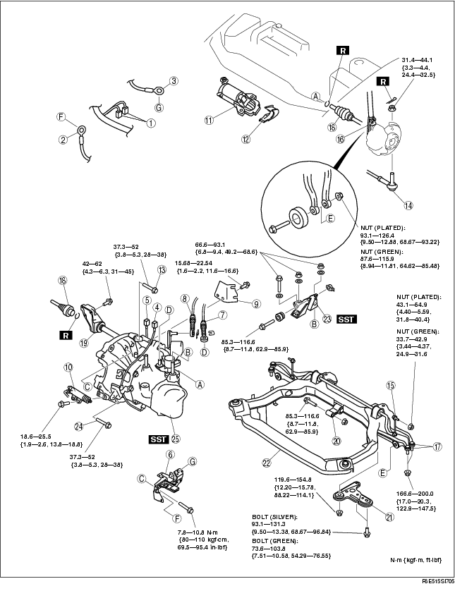
6. Remove in the order indicated in the table.
7. Install in the reverse order of removal.
8. Adjust the headlight zeroset. (See HEADLIGHT ZEROSET.)
9. Add the specified amount of specified transaxle oil.
10. Warm up the engine and transaxle, inspect for oil leakage, and inspect the transaxle operation.
.
|
1
|
A/F sensor connector, HO2S connector
|
|
2
|
GND wiring harness
|
|
3
|
GND wiring harness
|
|
4
|
Back-up light switch connector
|
|
5
|
Neutral switch connector
|
|
6
|
Harness bracket
|
|
7
|
Shift cable
|
|
8
|
Select cable
|
|
9
|
Cable bracket
|
|
10
|
Clutch release cylinder
|
|
11
|
Starter
|
|
12
|
Endplate cover
|
|
13
|
Transaxle mounting bolt (upper side)
|
|
14
|
Tie-rod end ball joint
|
|
15
|
Stabilizer control link
|
|
16
|
Damper fork
|
|
17
|
Lower arm (front, rear) ball joint
|
|
18
|
Drive shaft
|
|
19
|
Joint shaft
|
|
20
|
No.1 engine mount
|
|
21
|
Crossmember bracket
|
|
22
|
Crossmember component
|
|
23
|
No.4 engine mount
|
|
24
|
Transaxle mounting bolt (lower side)
|
|
25
|
Manual transaxle
|
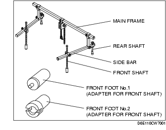
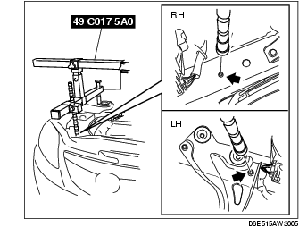
No.4 Engine Mount Bracket Removal Note
1. Install the SST using the following procedure.
-
Caution
-
• Refer to the SST instruction manual for the basic handing procedure.
-
(1) Install the right rear shaft of the SST to the bolt of the right shock absorber as shown in the figure.
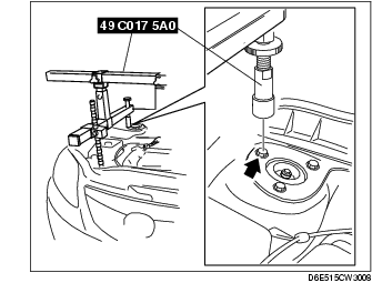
-
(2) Install the left rear shaft of the SST to the bolt of the left shock absorber. (Identical position to the right side)
-
(3) Install the left/right front shaft of the SST with front foot No.2 to the bolt as shown in the figure.
-
(4) Adjust the positions of the SST side bars so that they are the same height (left and right) and horizontal.
-
(5) Make sure each joint is securely tightened.
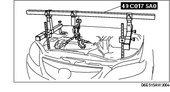
2. Support the engine using the SST.
-
Note
-
• The SST (49 E017 5A0) can be used in place of the SST (49 C017 5A0).
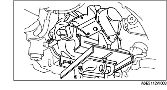
3. Remove the No.4 engine mount bracket.
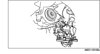
Manual Transaxle Removal Note
1. Lean the engine toward the transaxle.
2. Support the transaxle on a jack.
3. Remove the transaxle mounting bolts.
4. Remove the transaxle.
Manual Transaxle Installation Note
1. Set the transaxle on a jack and lift into place.
2. Install the transaxle mounting bolts.
3. Adjust the SST (49 C017 5A0) so that the engine is located at the specified position.
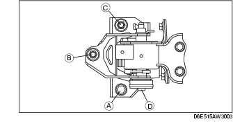
No.1 Engine Mount and No.4 Engine Mount Bracket Installation Note
1. Verify that the engine mount rubbers are installed as shown in the figure.
2. By aligning the holes with the stud bolts, install the No.4 engine mount bracket to the transaxle.
3. By aligning the holes with the stud bolts, install the No.1 engine mount to the transaxle.
4. Align the hole of the No.4 engine mount bracket with the No.4 engine mount rubber on vehicle, and temporarily tighten the bolt D.
5. Tighten the nut B,C in order of B→C, then bolt A.
6. Tighten the bolt D.
Tightening torque
-
A, B, C: 66.6-93.1 N·m
-
{6.8-9.4 kgf·m, 49.2-68.6 ft·lbf}
-
D: 85.3-116.6 N·m
-
{8.7-11.8 kgf·m, 62.9-85.9 ft·lbf}
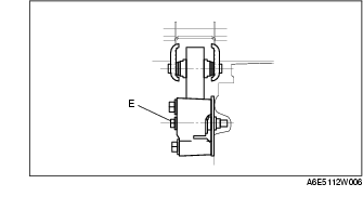
7. Tighten the bolt E to the No.1 engine mount.
Tightening torque
-
E: 85.3-116.6 N·m
-
{8.7-11.8 kgf·m, 62.9-85.9 ft·lbf}
8. Remove the SST (49 C017 5A0).