|
1
|
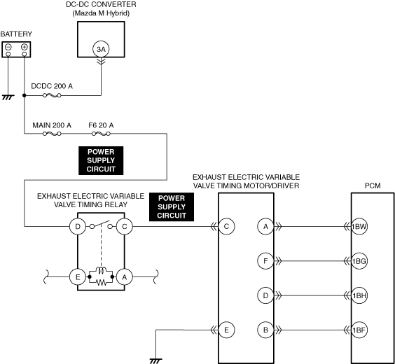
PURPOSE: INSPECT EXHAUST ELECTRIC VARIABLE VALVE TIMING RELAY POWER SUPPLY CIRCUIT FOR SHORT TO GROUND AND OPEN CIRCUIT
• Inspect the power supply circuit for an open circuit and short to ground.
• Is the circuit normal?
|
Yes
|
Go to the next step.
|
|
No
|
Repair or replace the malfunctioning location and perform the repair completion verification.
|
|
2
|
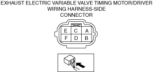
PURPOSE: INSPECT EXHAUST ELECTRIC VARIABLE VALVE TIMING MOTOR/DRIVER CONNECTOR FOR MALFUNCTION
• Inspect the applicable connector and terminal.
• Are the connector and terminal normal?
|
Yes
|
Go to the next step.
|
|
No
|
Repair or replace the malfunctioning location and perform the repair completion verification.
|
|
3
|
PURPOSE: INSPECT EXHAUST ELECTRIC VARIABLE VALVE TIMING MOTOR/DRIVER POWER SUPPLY CIRCUIT FOR SHORT TO GROUND
• Inspect the applicable circuit for a short to ground.
• Is the circuit normal?
|
Yes
|
Go to the next step.
|
|
No
|
Repair or replace the malfunctioning location and perform the repair completion verification.
|
|
4
|
PURPOSE: INSPECT EXHAUST ELECTRIC VARIABLE VALVE TIMING MOTOR/DRIVER POWER SUPPLY CIRCUIT FOR OPEN CIRCUIT
• Inspect the applicable circuit for open circuit.
• Is the circuit normal?
|
Yes
|
Go to the next step.
|
|
No
|
Repair or replace the malfunctioning location and perform the repair completion verification.
|
|
5
|
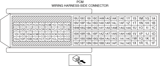
PURPOSE: INSPECT PCM CONNECTOR FOR MALFUNCTION
• Inspect the applicable connector and terminal.
• Are the connector and terminal normal?
|
Yes
|
Go to the next step.
|
|
No
|
Repair or replace the malfunctioning location and perform the repair completion verification.
|
|
6
|
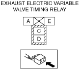
PURPOSE: INSPECT EXHAUST ELECTRIC VARIABLE VALVE TIMING RELAY FOR MALFUNCTION
• Inspect the applicable part.
• Is the part normal?
|
Yes
|
Go to the next step.
|
|
No
|
Repair or replace the malfunctioning location and perform the repair completion verification.
|
|
7
|
PURPOSE: INSPECT EXHAUST ELECTRIC VARIABLE VALVE TIMING MOTOR FOR MALFUNCTION
• Inspect the applicable part.
• Is the part normal?
|
Yes
|
Go to the next step.
|
|
No
|
Repair or replace the malfunctioning location and perform the repair completion verification.
|
|
8
|
PURPOSE: INSPECT EXHAUST ELECTRIC VARIABLE VALVE TIMING ACTUATOR FOR MALFUNCTION
• Inspect the applicable part.
• Is the part normal?
|
Yes
|
Go to the next step.
|
|
No
|
Repair or replace the malfunctioning location and perform the repair completion verification.
|
|
9
|
PURPOSE: VERIFY ASSEMBLY CONDITION OF TIMING CHAIN
• Verify the condition of the timing chain assembly (exhaust valve timing, looseness, jumping).
• Is there any malfunction?
|
Yes
|
Repair or replace the malfunctioning part.
Assemble the timing chain using the correct timing.
Go to repair completion verification.
|
|
No
|
Go to the next step.
|
|
10
|
PURPOSE: VERIFY IF FOREIGN MATTER ON EXHAUST CMP SENSOR DETECTION AREA AFFECTS DIAGNOSTIC RESULTS
• Visually inspect for exhaust CMP sensor.
• Is there foreign matter such as metallic dust on the exhaust CMP sensor detection area?
|
Yes
|
Remove the foreign matter and perform the repair completion verification.
|
|
No
|
Go to the next step.
|
|
11
|
PURPOSE: VERIFY IF FOREIGN MATTER ON CKP SENSOR DETECTION AREA AFFECTS DIAGNOSTIC RESULTS
• Visually inspect for CKP sensor.
• Is there foreign matter such as metallic dust on the CKP sensor detection area?
|
Yes
|
Remove the foreign matter and perform the repair completion verification.
|
|
No
|
Go to the next step.
|
|
Repair completion verification 1
|
PURPOSE: VERIFY THAT VEHICLE IS REPAIRED
• Install/connect the part removed/disconnected during the troubleshooting procedure.
• Clear the DTC recorded in the memory.
• Replicate the vehicle conditions at the time the DTC was detected using the following procedure.
-
― Implement the repeatability verification procedure.
• Perform the DTC inspection for the PCM.
• Is the same Pending DTC present?
|
Yes
|
Refer to the controller area network (CAN) malfunction diagnosis flow to inspect for a CAN communication error.
If the CAN communication is normal, perform the diagnosis from Step 1.
• If the malfunction recurs, replace the PCM, then go to the next step.
|
|
No
|
Go to the next step.
|
|
Repair completion verification 2
|
PURPOSE: VERIFY IF OTHER DTCs DISPLAYED
• Perform the DTC inspection.
• Are any other DTCs displayed?
|
Yes
|
Repair the malfunctioning location according to the applicable DTC troubleshooting.
|
|
No
|
DTC troubleshooting completed.
|