Home

Mazdamanuals.com

DTC P26A3:00 [PCM (SKYACTIV-X)]

DTC P26A3:00 [PCM (SKYACTIV-X)]


 id0102u9432400

Note
•  To determine the malfunctioning part, proceed with the diagnostics from "Function Inspection Using M-MDS".

Details On DTCs

Description

Coolant switching valve (CSV): Performance problem

Detection condition
Determination conditions
•  The state in which the water pressure sensor signal does not fluctuate when the engine coolant switching valve is closed occurs 10 times continuously
Preconditions
•  Engine speed: 2,000 rpm or more*1
•  The following DTCs are not detected:
―  Coolant switching valve: P2B5A:00 and P2B5B:00
―  Water pressure sensor: P05C4:00 and P05C5:00
*1: Standard can be verified by displaying PIDs using M-MDS
Malfunction determination period
•  Not applicable
Drive cycle
•  1
Self test type
•  CMDTC self test, KOER self test
Sensor used
•  Water pressure sensor
Fail-safe function
•  Fully open the coolant switching valve.
•  Inhibits the EGR control.
•  Turn on the electric thermostat heater.
•  Limits intake air amount.
Vehicle status when DTCs are output
•  Not applicable
Possible cause
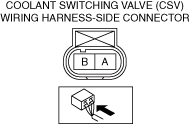
•  Coolant switching valve connector or terminals malfunction
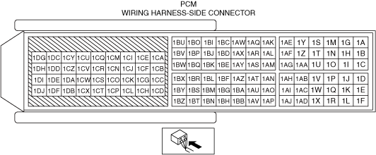
•  PCM connector or terminals malfunction
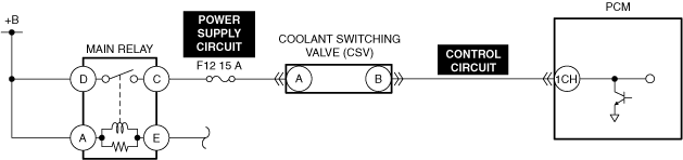
•  Short to ground in any of the following coolant switching valve circuits.
―  Power supply circuit
―  Control circuit
•  Open circuit in any of the following coolant switching valve circuits.
―  Power supply circuit
―  Control circuit
•  Short to power supply in coolant switching valve control circuit
•  Short circuit in coolant switching valve power supply circuit and control circuit
•  Coolant switching valve malfunction
•  Trapped air in engine coolant passage
•  Electric water pump malfunction
•  Drive belt loss, deviation or wear
•  PCM malfunction


Function Explanation (DTC Detection Outline)

•  The PCM adjusts the engine coolant flow volume by opening/closing the coolant switching valve according to the engine conditions.
•  The PCM measures the pressure using the water pressure sensor installed upstream of the coolant switching valve.
•  When the coolant switching valve is closed while the engine is running, the water flow is cut off momentarily and the pressure upstream of the coolant switching valve fluctuates.
•  If the water pressure sensor pressure does not fluctuate even though the PCM requests the coolant switching valve to open during cold temperatures, the PCM determines that the coolant switching valve is stuck and stores a DTC.

Repeatability Verification Procedure

1.  Start the engine and allow the engine coolant temperature to reach 20 °C {68 °F} or more.

2.  Shift to the N position (ATX)/N position (MTX) and maintain the engine speed at 4,000 rpm or more for 1 s or more.

3.  Maintain the engine speed between 2,500 and 3,000 rpm for 1 min.


PID Item/Simulation Item Used In Diagnosis

PID/DATA monitor item table

PIDs

Reference

ENG_COOL_VLV_POS_ACT

Simulation item table

Simulation items

Reference

ENG_COOL_VLV_POS_DUTY


Function Inspection Using M-MDS

Step

Inspection

Results

Action

1
PURPOSE: VERIFY RELATED REPAIR INFORMATION OR SERVICE INFORMATION AVAILABILITY
•  Verify related Service Bulletins, on-line repair information, or Service Information availability.
•  Is any related Information available?
Yes
Perform repair or diagnosis according to the available information.
•  If the vehicle is not repaired, go to the next step.
No
Go to the next step.
2
PURPOSE: IDENTIFY TRIGGER DTC FOR FREEZE FRAME DATA
•  Is the DTC P26A3:00 on freeze frame data?
Yes
Go to the next step.
No
Go to the troubleshooting procedure for DTC on freeze frame data.
3
PURPOSE: RECORD VEHICLE STATUS WHEN DTC WAS DETECTED TO UTILIZE WITH REPEATABILITY VERIFICATION
•  Record the freeze frame data/snapshot data.
Note
•  Recording can be facilitated using the screen capture function of the PC.
Go to the next step.
4
PURPOSE: INSPECT FOR OTHER RELATED DTCs
•  Perform the DTC inspection for the PCM.
•  Are any other DTCs displayed?
Yes
Repair the malfunctioning location according to the applicable DTC troubleshooting.
Go to the next step.
No
Go to the next step.
5
PURPOSE: VERIFY CONFORMITY OF ACTUAL COOLANT SWITCHING VALVE
•  Switch the ignition ON (engine off).
•  Access the following PIDs using the M-MDS:
PID item
―  ENG_COOL_VLV_POS_ACT
Simulation item
―  ENG_COOL_VLV_POS_DUTY
•  Perform the following:
1.  Change the simulation item ENG_COOL_VLV_POS_DUTY between 0% and 100%.
2.  Verify that the ENG_COOL_VLV_POS_ACT monitor value conforms to the simulation item ENG_COOL_VLV_POS_DUTY.
•  Does the monitor value of the PID item ENG_COOL_VLV_POS_ACT conform to the ENG_COOL_VLV_POS_DUTY monitor value?
Yes
Go to the next step.
No
Go to Troubleshooting Diagnostic Procedure to perform the procedure from Step 1.
6
PURPOSE: VERIFY CONNECTOR CONNECTIONS
•  Start the engine.
•  Access the ENG_COOL_VLV_POS_ACT PID using the M-MDS.
•  Does the PID value fluctuate when the following connectors are shaken?
―  Coolant switching valve
―  PCM
Yes
Repair or replace the applicable wiring harness or connector parts.
Go to Troubleshooting Diagnostic Procedure to perform the procedure from Step 5.
No
Go to Troubleshooting Diagnostic Procedure to perform the procedure from Step 1.


Troubleshooting Diagnostic Procedure

Intention of troubleshooting procedure
•  Step 1—4
―  Perform an inspection of the connectors and wiring harnesses between the coolant switching valve and the PCM.
•  Step 5
―  Perform a unit inspection of the coolant switching valve.
•  Step 6—8
―  Perform an inspection of the cooling system component part malfunction.
•  Repair completion verification
―  Verify that the primary malfunction is resolved and there are no other malfunctions.

Step

Inspection

Results

Action

1
INSPECT COOLANT SWITCHING VALVE POWER SUPPLY CIRCUIT AND CONTROL CIRCUIT FOR SHORT TO GROUND
•  Inspect the applicable circuit for a short to ground.
•  Is the circuit normal?
Yes
Go to the next step.
No
Repair or replace the malfunctioning location and perform the repair completion verification.
2
INSPECT COOLANT SWITCHING VALVE POWER SUPPLY CIRCUIT AND CONTROL CIRCUIT FOR OPEN CIRCUIT
•  Inspect the applicable circuit for open circuit.
•  Is the circuit normal?
Yes
Go to the next step.
No
Repair or replace the malfunctioning location and perform the repair completion verification.
3
INSPECT COOLANT SWITCHING VALVE POWER SUPPLY CIRCUIT AND CONTROL CIRCUIT FOR SHORT TO POWER SUPPLY
•  Inspect the applicable circuit for a short to power supply.
•  Is the circuit normal?
Yes
Go to the next step.
No
Repair or replace the malfunctioning location and perform the repair completion verification.
4
INSPECT COOLANT SWITCHING VALVE POWER SUPPLY CIRCUIT AND CONTROL CIRCUIT FOR SHORT CIRCUIT
•  Inspect the applicable circuits for a short circuit.
•  Is the circuit normal?
Yes
Go to the next step.
No
Repair or replace the malfunctioning location and perform the repair completion verification.
5
INSPECT COOLANT SWITCHING VALVE
•  Inspect the applicable part.
•  Is the part normal?
Yes
Go to the next step.
No
Repair or replace the malfunctioning location and perform the repair completion verification.
6
BLEED AIR FROM ENGINE COOLANT PASSAGE
•  Bleed the air according to the engine coolant air bleeding procedure.
Go to the next step.
7
INSPECT ELECTRIC WATER PUMP
•  Inspect the applicable part.
•  Is the part normal?
Yes
Go to the next step.
No
Repair or replace the malfunctioning location and perform the repair completion verification.
8
INSPECT DRIVE BELT
•  Inspect the applicable part.
•  Is the part normal?
Yes
Go to the next step.
No
Repair or replace the malfunctioning location and perform the repair completion verification.
Repair completion verification 1
VERIFY THAT VEHICLE IS REPAIRED
•  Install/connect the part removed/disconnected during the troubleshooting procedure.
•  Clear the DTC recorded in the memory.
•  Replicate the vehicle conditions at the time the DTC was detected using the following procedure.
―  Implement the repeatability verification procedure.
•  Perform the DTC inspection for the PCM.
•  Is the same Pending DTC present?
Yes
Refer to the controller area network (CAN) malfunction diagnosis flow to inspect for a CAN communication error.
If the CAN communication is normal, perform the diagnosis from Step 1.
•  If the malfunction recurs, replace the PCM, then go to the next step.
No
Go to the next step.
Repair completion verification 2
VERIFY IF OTHER DTCs DISPLAYED
•  Perform the DTC inspection.
•  Are any other DTCs displayed?
Yes
Repair the malfunctioning location according to the applicable DTC troubleshooting.
No
DTC troubleshooting completed.