ac30zw00003447
|
POWER BRAKE UNIT REMOVAL/INSTALLATION [R.H.D.]
id041100801852
Replacement Part
|
Gasket
Quantity: 1
Location of use: Power brake unit
|
Brake switch
Quantity: 1
Location of use: Brake pedal
|
Oil and Chemical Type
|
Brake fluid type
Type: SAE J1703 or FMVSS116 DOT-3 or DOT-4
|
1. Disconnect the negative battery terminal. (See NEGATIVE BATTERY TERMINAL DISCONNECTION/CONNECTION [(E)].)
2. Remove the following parts:
3. Remove the insulator. (See EXHAUST SYSTEM REMOVAL/INSTALLATION [SKYACTIV-G (WITHOUT CYLINDER DEACTIVATION (E))].)(See EXHAUST SYSTEM REMOVAL/INSTALLATION [SKYACTIV-G (WITH CYLINDER DEACTIVATION (E))].)(See EXHAUST SYSTEM REMOVAL/INSTALLATION [SKYACTIV-D 1.8].)
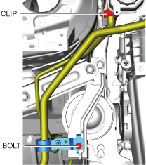
4. For SKYACTIV-G 2.0 or SKYACTIV-G 2.5 perform the following procedure:
ac30zw00003447
|
5. Remove the master cylinder. (See MASTER CYLINDER REMOVAL/INSTALLATION [R.H.D.].)
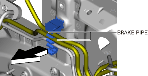
6. Detach the brake pipes from the clip.
am3zzw00029772
|
7. For SKYACTIV-D 1.8, perform the following procedure:
am3zzw00029771
|
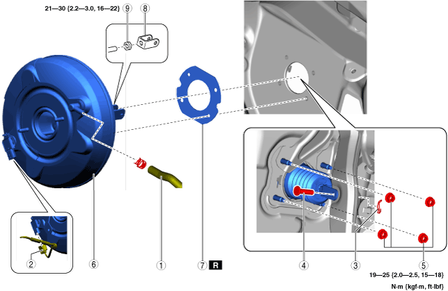
8. Remove in the order indicated in the table.
9. Install in the reverse order of removal.
10. After installation, add brake fluid, bleed the air, and inspect for fluid leakage. (See BRAKE FLUID AIR BLEEDING [(E)].) (See CLUTCH FLUID REPLACEMENT/AIR BLEEDING [C66M-R, C66MX-R] (MTX).)
11. Remove the brake switch. (See BRAKE PEDAL REMOVAL/INSTALLATION [R.H.D.].)
12. Inspect the brake pedal. (See BRAKE PEDAL REMOVAL/INSTALLATION [R.H.D.].)
13. Install a new brake switch. (See BRAKE PEDAL REMOVAL/INSTALLATION [R.H.D.].)
ac30zw00004082
|
|
1
|
Vacuum hose
|
|
2
|
Power brake unit vacuum sensor connector (With i-stop)
|
|
3
|
Snap pin
|
|
4
|
Clevis pin
|
|
5
|
Nut
|
|
6
|
Fork
(See Fork Installation Note.)
|
|
7
|
Locknut
|
|
8
|
Power brake unit
|
|
9
|
Gasket
|
Power Brake Unit Removal Note [SKYACTIV-D 1.8]
1. Remove the fork and locknut.
2. Remove the power brake unit.
Power Brake Unit Installation Note [SKYACTIV-D 1.8]
1. Install the power brake unit.
2. Install the fork and locknut. (See Fork Installation Note.)
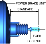
Fork Installation Note
1. Install the fork as shown in the figure.
am3zzw00025072
|