 |
ac30zw00002385
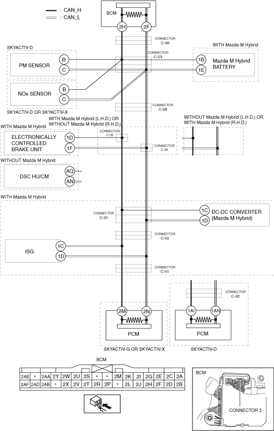
DETERMINING SHORT TO POWER SUPPLY LOCATION (CAN-BUS No.2) [(E)]
id1002x2002300
System Wiring Diagram
ac30zw00002385
|
Determination Procedure (With Mazda M Hybrid or SKYACTIV-D or SKYACTIV-X)
|
Step |
Inspection |
Action |
|
|---|---|---|---|
|
1
|
INSPECT BODY CONTROL MODULE (BCM) FOR SHORT TO POWER SUPPLY
• Switch the ignition off.
• Disconnect the negative battery terminal.
• Disconnect the connector 2 which has body control module (BCM) terminals 2H and 2F.
• Connect the negative battery terminal.
• Switch the ignition ON (engine off).
• Measure the voltage at body control module (BCM) terminals 2H and 2F (wiring harness side).
• Is the voltage between 1.5—3.5 V?
|
Yes
|
Replace the body control module (BCM) because there is a short to the power supply in the body control module (BCM).
|
|
No
|
Go to the next step.
|
||
|
2
|
INSPECT CAN LINE BETWEEN BODY CONTROL MODULE (BCM) AND CONNECTOR C-09 FOR SHORT TO POWER SUPPLY
• Switch the ignition off.
• Disconnect the negative battery terminal.
• Disconnect the connector C-09.
• Connect the negative battery terminal.
• Switch the ignition ON (engine off).
• Measure the voltage at body control module (BCM) terminals 2H and 2F.
• Is the voltage between 1.5—3.5 V?
|
Yes
|
Go to the next step.
|
|
No
|
Repair or replace the wiring harness between the body control module (BCM) and connector C-09 because the wiring harness is shorted to the power supply.
|
||
|
3
|
INSPECT CAN LINE BETWEEN CONNECTOR C-53 AND CONNECTOR C-09 FOR SHORT TO POWER SUPPLY
• Switch the ignition off.
• Disconnect the negative battery terminal.
• Disconnect the connector C-53.
• Connect the connector C-09.
• Connect the negative battery terminal.
• Switch the ignition ON (engine off).
• Measure the voltage at body control module (BCM) terminals 2H and 2F.
• Is the voltage between 1.5—3.5 V?
|
Yes
|
Go to the next step.
|
|
No
|
Repair or replace the wiring harness between the connector C-53 and connector C-09 because the wiring harness is shorted to the power supply.
|
||
|
4
|
INSPECT CAN LINE BETWEEN PM SENSOR AND CONNECTOR C-53 FOR SHORT TO POWER SUPPLY
• Measure the voltage at PM sensor terminals B and C.
• Is the voltage between 1.5—3.5 V?
|
Yes
|
Go to Step 6.
|
|
No
|
Go to the next step.
|
||
|
5
|
INSPECT PM SENSOR FOR SHORT TO POWER SUPPLY
• Switch the ignition off.
• Disconnect the negative battery terminal.
• Disconnect the PM sensor connector.
• Connect the connector C-53.
• Connect the negative battery terminal.
• Switch the ignition ON (engine off).
• Measure the voltage at body control module (BCM) terminals 2H and 2F.
• Is the voltage between 1.5—3.5 V?
|
Yes
|
Replace the PM sensor because there is a short to the power supply in the PM sensor.
|
|
No
|
Repair or replace the wiring harness between the PM sensor and connector C-53 because the wiring harness is shorted to the power supply.
|
||
|
6
|
INSPECT CAN LINE BETWEEN NOx SENSOR AND CONNECTOR C-53 FOR SHORT TO POWER SUPPLY
• Measure the voltage at NOx sensor terminals B and C.
• Is the voltage between 1.5—3.5 V?
|
Yes
|
Go to Step 8.
|
|
No
|
Go to the next step.
|
||
|
7
|
INSPECT NOx SENSOR FOR SHORT TO POWER SUPPLY
• Switch the ignition off.
• Disconnect the negative battery terminal.
• Disconnect the NOx sensor connector.
• Connect the connector C-53.
• Connect the negative battery terminal.
• Switch the ignition ON (engine off).
• Measure the voltage at body control module (BCM) terminals 2H and 2F.
• Is the voltage between 1.5—3.5 V?
|
Yes
|
Replace the NOx sensor because there is a short to the power supply in the NOx sensor.
|
|
No
|
Repair or replace the wiring harness between the NOx sensor and connector C-53 because the wiring harness is shorted to the power supply.
|
||
|
8
|
INSPECT CAN LINE BETWEEN Mazda M Hybrid BATTERY AND CONNECTOR C-53 FOR SHORT TO POWER SUPPLY
• Measure the voltage at Mazda M Hybrid battery terminals 1B and 1E.
• Is the voltage between 1.5—3.5 V?
|
Yes
|
Go to Step 10.
|
|
No
|
Go to the next step.
|
||
|
9
|
INSPECT Mazda M Hybrid BATTERY FOR SHORT TO POWER SUPPLY
• Switch the ignition off.
• Disconnect the negative battery terminal.
• Disconnect the Mazda M Hybrid battery connector.
• Connect the connector C-53.
• Connect the negative battery terminal.
• Switch the ignition ON (engine off).
• Measure the voltage at body control module (BCM) terminals 2H and 2F.
• Is the voltage between 1.5—3.5 V?
|
Yes
|
Replace the Mazda M Hybrid battery because there is a short to the power supply in the Mazda M Hybrid battery.
|
|
No
|
Repair or replace the wiring harness between the Mazda M Hybrid battery and connector C-53 because the wiring harness is shorted to the power supply.
|
||
|
10
|
INSPECT CAN LINE BETWEEN CONNECTOR C-08 AND CONNECTOR C-53 FOR SHORT TO POWER SUPPLY
• Switch the ignition off.
• Disconnect the negative battery terminal.
• Disconnect the connector C-08.
• Connect the connector C-53.
• Connect the negative battery terminal.
• Switch the ignition ON (engine off).
• Measure the voltage at body control module (BCM) terminals 2H and 2F.
• Is the voltage between 1.5—3.5 V?
|
Yes
|
• Go to the next step. (L.H.D.)
• Go to Step 15. (R.H.D.)
|
|
No
|
Repair or replace the wiring harness between the connector C-08 and connector C-53 because the wiring harness is shorted to the power supply.
|
||
|
11
|
INSPECT CAN LINE BETWEEN CONNECTORS C-35, C-34 AND CONNECTOR C-08 FOR SHORT TO POWER SUPPLY
• Switch the ignition off.
• Disconnect the negative battery terminal.
• Disconnect the connectors C-35, C-34.
• Connect the connector C-08.
• Connect the negative battery terminal.
• Switch the ignition ON (engine off).
• Measure the voltage at body control module (BCM) terminals 2H and 2F.
• Is the voltage between 1.5—3.5 V?
|
Yes
|
Go to the next step.
|
|
No
|
Repair or replace the wiring harness between the connectors C-35, C-34 and connector C-08 because the wiring harness is shorted to the power supply.
|
||
|
12
|
INSPECT CAN LINE BETWEEN ELECTRONICALLY CONTROLLED BRAKE UNIT AND CONNECTORS C-35, C-34 FOR SHORT TO POWER SUPPLY
• Measure the voltage at electronically controlled brake unit terminals 1D and 1F.
• Is the voltage between 1.5—3.5 V?
|
Yes
|
Go to Step 14.
|
|
No
|
Go to the next step.
|
||
|
13
|
INSPECT ELECTRONICALLY CONTROLLED BRAKE UNIT FOR SHORT TO POWER SUPPLY
• Switch the ignition off.
• Disconnect the negative battery terminal.
• Disconnect the electronically controlled brake unit connector.
• Connect the connectors C-35, C-34.
• Connect the negative battery terminal.
• Switch the ignition ON (engine off).
• Measure the voltage at body control module (BCM) terminals 2H and 2F.
• Is the voltage between 1.5—3.5 V?
|
Yes
|
Replace the electronically controlled brake unit because there is a short to the power supply in the electronically controlled brake unit.
|
|
No
|
Repair or replace the wiring harness between the electronically controlled brake unit and connectors C-35, C-34 because the wiring harness is shorted to the power supply.
|
||
|
14
|
INSPECT CAN LINE BETWEEN CONNECTOR C-31 AND CONNECTORS C-35, C-34 FOR SHORT TO POWER SUPPLY
• Switch the ignition off.
• Disconnect the negative battery terminal.
• Disconnect the connector C-31.
• Connect the connectors C-35, C-34.
• Connect the negative battery terminal.
• Switch the ignition ON (engine off).
• Measure the voltage at body control module (BCM) terminals 2H and 2F.
• Is the voltage between 1.5—3.5 V?
|
Yes
|
Go to Step 17.
|
|
No
|
Repair or replace the wiring harness between connector C-31 and connectors C-35, C-34 because the wiring harness is shorted to the power supply.
|
||
|
15
|
INSPECT CAN LINE BETWEEN CONNECTOR C-08 AND CONNECTOR C-31 FOR SHORT TO POWER SUPPLY
• Switch the ignition off.
• Disconnect the negative battery terminal.
• Disconnect the connector C-31.
• Connect the connector C-08.
• Connect the negative battery terminal.
• Switch the ignition ON (engine off).
• Measure the voltage at body control module (BCM) terminals 2H and 2F.
• Is the voltage between 1.5—3.5 V?
|
Yes
|
Go to Step 17.
|
|
No
|
Go to the next step.
|
||
|
16
|
INSPECT ELECTRONICALLY CONTROLLED BRAKE UNIT FOR SHORT TO POWER SUPPLY
• Switch the ignition off.
• Disconnect the negative battery terminal.
• Disconnect the electronically controlled brake unit connector.
• Connect the negative battery terminal.
• Switch the ignition ON (engine off).
• Measure the voltage at body control module (BCM) terminals 2H and 2F.
• Is the voltage between 1.5—3.5 V?
|
Yes
|
Replace the electronically controlled brake unit because there is a short to the power supply in the electronically controlled brake unit.
|
|
No
|
Repair or replace the wiring harness between the connector C-08 and connector C-31 because the wiring harness is shorted to the power supply.
|
||
|
17
|
INSPECT CAN LINE BETWEEN DC-DC CONVERTER (Mazda M Hybrid) AND CONNECTOR C-31 FOR SHORT TO POWER SUPPLY
• Measure the voltage at DC-DC converter (Mazda M Hybrid) terminals 1C and 1D.
• Is the voltage between 1.5—3.5 V?
|
Yes
|
Go to Step 19.
|
|
No
|
Go to the next step.
|
||
|
18
|
INSPECT DC-DC CONVERTER (Mazda M Hybrid) FOR SHORT TO POWER SUPPLY
• Switch the ignition off.
• Disconnect the negative battery terminal.
• Disconnect the DC-DC converter (Mazda M Hybrid) connector.
• Connect the connector C-31.
• Connect the negative battery terminal.
• Switch the ignition ON (engine off).
• Measure the voltage at body control module (BCM) terminals 2H and 2F.
• Is the voltage between 1.5—3.5 V?
|
Yes
|
Replace the DC-DC converter (Mazda M Hybrid) because there is a short to the power supply in the DC-DC converter (Mazda M Hybrid).
|
|
No
|
Repair or replace the wiring harness between the DC-DC converter (Mazda M Hybrid) and connector C-31 because the wiring harness is shorted to the power supply.
|
||
|
19
|
INSPECT CAN LINE BETWEEN CONNECTOR C-02 AND CONNECTOR C-31 FOR SHORT TO POWER SUPPLY
• Switch the ignition off.
• Disconnect the negative battery terminal.
• Disconnect the connector C-02.
• Connect the connector C-31.
• Connect the negative battery terminal.
• Switch the ignition ON (engine off).
• Measure the voltage at body control module (BCM) terminals 2H and 2F.
• Is the voltage between 1.5—3.5 V?
|
Yes
|
Go to the next step.
|
|
No
|
Repair or replace the wiring harness between connector C-02 and connector C-31 because the wiring harness is shorted to the power supply.
|
||
|
20
|
INSPECT CAN LINE BETWEEN CONNECTOR C-02 AND CONNECTOR C-01 FOR SHORT TO POWER SUPPLY
• Switch the ignition off.
• Disconnect the negative battery terminal.
• Disconnect the connector C-01.
• Connect the connector C-02.
• Connect the negative battery terminal.
• Switch the ignition ON (engine off).
• Measure the voltage at body control module (BCM) terminals 2H and 2F.
• Is the voltage between 1.5—3.5 V?
|
Yes
|
• Go to Step 22.(SKYACTIV-G or SKYACTIV-X)
• Go to Step 23.(SKYACTIV-D)
|
|
No
|
Go to the next step.
|
||
|
21
|
INSPECT INTEGRATED STARTER GENERATOR (ISG) FOR SHORT TO POWER SUPPLY
• Switch the ignition off.
• Disconnect the negative battery terminal.
• Disconnect the integrated starter generator (ISG) connector.
• Connect the negative battery terminal.
• Switch the ignition ON (engine off).
• Measure the voltage at body control module (BCM) terminals 2H and 2F.
• Is the voltage between 1.5—3.5 V?
|
Yes
|
Replace the integrated starter generator (ISG) because there is a short to the power supply in the integrated starter generator (ISG).
|
|
No
|
Repair or replace the wiring harness between the connector C-02 and connector C-01 / integrated starter generator (ISG) because the wiring harness is shorted to the power supply.
|
||
|
22
|
INSPECT PCM FOR SHORT TO POWER SUPPLY
• Switch the ignition off.
• Disconnect the negative battery terminal.
• Disconnect the PCM connector.
• Connect the connector C-01.
• Connect the negative battery terminal.
• Switch the ignition ON (engine off).
• Measure the voltage at body control module (BCM) terminals 2H and 2F.
• Is the voltage between 1.5—3.5 V?
|
Yes
|
Replace the PCM because there is a short to the power supply in the PCM.
|
|
No
|
Repair or replace the wiring harness between the PCM and connector C-01 because the wiring harness is shorted to the power supply.
|
||
|
23
|
INSPECT CAN LINE BETWEEN CONNECTOR C-02 AND PCM FOR SHORT TO POWER SUPPLY
• Switch the ignition off.
• Disconnect the negative battery terminal.
• Disconnect the connector C-02.
• Connect the negative battery terminal.
• Switch the ignition ON (engine off).
• Measure the voltage at PCM terminals 1AI and 1AN.
• Is the voltage between 1.5—3.5 V?
|
Yes
|
Repair or replace the wiring harness between the connector C-01 and connector C-02 because the wiring harness is shorted to the power supply.
|
|
No
|
Go to the next step.
|
||
|
24
|
INSPECT PCM FOR SHORT TO POWER SUPPLY
• Switch the ignition off.
• Disconnect the negative battery terminal.
• Disconnect the PCM connector.
• Connect the connector C-02.
• Connect the connector C-01.
• Connect the negative battery terminal.
• Switch the ignition ON (engine off).
• Measure the voltage at body control module (BCM) terminals 2H and 2F.
• Is the voltage between 1.5—3.5 V?
|
Yes
|
Replace the PCM because there is a short to the power supply in the PCM.
|
|
No
|
Repair or replace the wiring harness between the PCM and connector C-02 because the wiring harness is shorted to the power supply.
|
||
Determination Procedure (Without Mazda M Hybrid and SKYACTIV-G)
|
Step |
Inspection |
Action |
|
|---|---|---|---|
|
1
|
INSPECT BODY CONTROL MODULE (BCM) FOR SHORT TO POWER SUPPLY
• Switch the ignition off.
• Disconnect the negative battery terminal.
• Disconnect the connector 2 which has body control module (BCM) terminals 2H and 2F.
• Connect the negative battery terminal.
• Switch the ignition ON (engine off).
• Measure the voltage at body control module (BCM) terminals 2H and 2F (wiring harness side).
• Is the voltage between 1.5—3.5 V?
|
Yes
|
Replace the body control module (BCM) because there is a short to the power supply in the body control module (BCM).
|
|
No
|
• Go to the next step. (R.H.D.)
• Go to Step 6. (L.H.D.)
|
||
|
2
|
INSPECT CAN LINE BETWEEN BODY CONTROL MODULE (BCM) AND CONNECTORS C-35, C-34 FOR SHORT TO POWER SUPPLY
• Switch the ignition off.
• Disconnect the negative battery terminal.
• Disconnect the connectors C-35, C-34.
• Connect the connector 2 which has body control module (BCM) terminals 2H and 2F.
• Connect the negative battery terminal.
• Switch the ignition ON (engine off).
• Measure the voltage at body control module (BCM) terminals 2H and 2F.
• Is the voltage between 1.5—3.5 V?
|
Yes
|
Go to the next step.
|
|
No
|
Repair or replace the wiring harness between the body control module (BCM) and connectors C-35, C-34 because the wiring harness is shorted to the power supply.
|
||
|
3
|
INSPECT CAN LINE BETWEEN DSC HU/CM AND CONNECTORS C-35, C-34 FOR SHORT TO POWER SUPPLY
• Measure the voltage at DSC HU/CM terminals AQ and AN.
• Is the voltage between 1.5—3.5 V?
|
Yes
|
Go to Step 5.
|
|
No
|
Go to the next step.
|
||
|
4
|
INSPECT DSC HU/CM FOR SHORT TO POWER SUPPLY
• Switch the ignition off.
• Disconnect the negative battery terminal.
• Disconnect the DSC HU/CM connector.
• Connect the connectors C-35, C-34.
• Connect the negative battery terminal.
• Switch the ignition ON (engine off).
• Measure the voltage at body control module (BCM) terminals 2H and 2F.
• Is the voltage between 1.5—3.5 V?
|
Yes
|
Replace the DSC HU/CM because there is a short to the power supply in the DSC HU/CM.
|
|
No
|
Repair or replace the wiring harness between the DSC HU/CM and connectors C-35, C-34 because the wiring harness is shorted to the power supply.
|
||
|
5
|
INSPECT CAN LINE BETWEEN CONNECTORS C-35, C-34 AND PCM FOR SHORT TO POWER SUPPLY
• Switch the ignition off.
• Disconnect the negative battery terminal.
• Disconnect the PCM connector.
• Connect the connectors C-35, C-34.
• Connect the negative battery terminal.
• Switch the ignition ON (engine off).
• Measure the voltage at body control module (BCM) terminals 2H and 2F.
• Is the voltage between 1.5—3.5 V?
|
Yes
|
Replace the PCM because there is a short to the power supply in the PCM.
|
|
No
|
Repair or replace the wiring harness between connectors C-35, C-34 and PCM because the wiring harness is shorted to the power supply.
|
||
|
6
|
INSPECT DSC HU/CM FOR SHORT TO POWER SUPPLY
• Switch the ignition off.
• Disconnect the negative battery terminal.
• Disconnect the DSC HU/CM connector.
• Connect the negative battery terminal.
• Switch the ignition ON (engine off).
• Measure the voltage at body control module (BCM) terminals 2H and 2F.
• Is the voltage between 1.5—3.5 V?
|
Yes
|
Replace the DSC HU/CM because there is a short to the power supply in the DSC HU/CM.
|
|
No
|
Go to the next step.
|
||
|
7
|
INSPECT PCM FOR SHORT TO POWER SUPPLY
• Switch the ignition off.
• Disconnect the negative battery terminal.
• Disconnect the PCM connector.
• Connect the negative battery terminal.
• Switch the ignition ON (engine off).
• Measure the voltage at body control module (BCM) terminals 2H and 2F.
• Is the voltage between 1.5—3.5 V?
|
Yes
|
Replace the PCM because there is a short to the power supply in the PCM.
|
|
No
|
Repair or replace the wiring harness between the DSC HU/CM and body control module (BCM) / PCM because the wiring harness is shorted to the power supply.
|
||